AIR CONDITIONING SYSTEM PTC Heater Circuit
DESCRIPTION
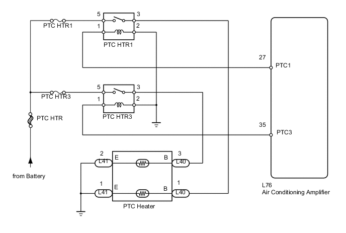
The PTC heater is installed in the radiator in the heater unit and operates when cooling water temperature is low and normal heater effectiveness is insufficient.
The air conditioning amplifier switches the circuit in the PTC relay and operates the PTC heater when the operating conditions (cooling water temperature is below 55°C (131°F), setting temperature is MAX. HOT, air outlet damper position is FOOT or FOOT/DEF, and blower switch is not OFF) are met.
WIRING DIAGRAM
PROCEDURE
-
INSPECT FUSE (PTC HTR1, PTC HTR3, PTC HTR)
-
Remove the PTC HTR1 and PTC HTR3 fuses from the engine room No. 4 relay block, and PTC HTR H-fuse from the engine room No. 1 junction block.
-
Measure the resistance according to the value(s) in the table below.
Standard resistance Tester Connection Condition Specified Condition PTC HTR1 fuse Always Below 1 Ω PTC HTR3 fuse PTC HTR H-fuse
NG 
REPLACE FUSE
OK 
-
-
CHECK AIR CONDITIONING AMPLIFIER
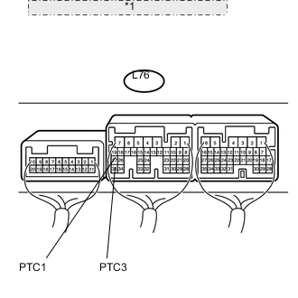
*1 Component with harness connected: (Air Conditioning Amplifier)
-
Remove the air conditioning amplifier with its connectors still connected Click here.
-
Measure the voltage according to the value(s) in the table below.
Standard voltage Tester Connection Condition Specified Condition L76-27 (PTC1) - Body ground Power switch ON (IG)
Temperature setting: MAX. HOT
MODE switch: FOOT
Engine coolant temperature: 55°C (131°F) or lower
Blower switch: OFF
11 to 14 V L76-35 (PTC3) - Body ground
NG
REPLACE AIR CONDITIONING AMPLIFIER Click here
OK
-
-
INSPECT PTC HEATER RELAY (PTC HTR1, PTC HTR3)
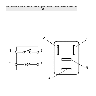
*a No. 1 and No. 3 PTC Heater Relays (PTC HTR1, PTC HTR3)
-
Remove the PTC heater relays from the No. 4 relay block.
-
Measure the resistance according to the value(s) in the table below.
Standard resistance Tester Connection Condition Specified Condition 3 - 5 When battery voltage is not applied between terminals 1 and 2 10 kΩ or higher When battery voltage is applied to terminals 1 and 2 Below 1 Ω
NG
REPLACE PTC HEATER RELAY
OK
-
-
CHECK HARNESS AND CONNECTOR (PTC HEATER RELAY - PTC HEATER)
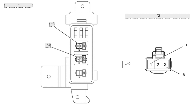
*1 No. 4 Relay Block *2 Front view of wire harness connector: (to PTC Heater) *3 No. 1 PTC Heater Relay (PTC HTR1) *4 No. 3 PTC Heater Relay (PTC HTR3)
-
Remove the PTC heater relays from the No. 4 relay block.
-
Disconnect the L40 PTC heater connector.
-
Measure the resistance according to the value(s) in the table below.
Standard resistance Tester Connection Condition Specified Condition PTC HTR1 terminal 3 - L40-1 (B) Always Below 1 Ω PTC HTR3 terminal 3 - L40-3 (B)
NG
REPAIR OR REPLACE HARNESS OR CONNECTOR
OK
-
-
CHECK PTC HEATER
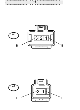
*1 Component without harness connected: (PTC Heater)
-
Disconnect the L40 and L41 PTC heater connectors.
-
Measure the resistance according to the value(s) in the table below.
Standard resistance Tester Connection Condition Specified Condition L40-1 (B) - L41-1 (E) Always Below 1 Ω L40-3 (B) - L41-2 (E)
NG
REPLACE PTC HEATER Click here
OK
-
-
CHECK HARNESS AND CONNECTOR (AIR CONDITIONING AMPLIFIER - BODY GROUND)
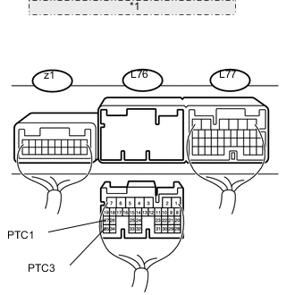
*1 Rear view of wire harness connector: (to Air Conditioning Amplifier)
-
Disconnect the L76 air conditioning amplifier connector.
-
Measure the resistance according to the value(s) in the table below.
Standard resistance Tester Connection Condition Specified Condition L76-27 (PTC1) - Body ground Always Below 1 Ω L76-35 (PTC3) - Body ground
OK
REPLACE AIR CONDITIONING AMPLIFIER Click here
NG
REPAIR OR REPLACE HARNESS OR CONNECTOR
-