FRONT SEAT OUTER BELT ASSEMBLY INSPECTION

PROCEDURE
-
INSPECT FRONT SEAT OUTER BELT ASSEMBLY
CAUTION:
Do not disassemble the retractor.
-
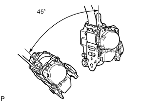
Before installing the seat belt, check the ELR.
-
When the inclination of the retractor is 15° or less, check that the belt can be pulled from the retractor. When the inclination of the retractor is over 45°, check that the belt locks. If the operation is not as specified, replace the seat belt assembly.
-
-
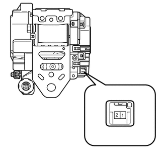
Check the tension reducer operation.
CAUTION:
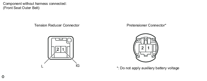
Do not apply battery voltage to the pretensioner connector.
-
Connect the auxiliary battery's positive (+) lead to terminal 1 (IG) of the tension reducer connector and the negative (-) lead to terminal 2 (L).
-
Check that an operating sound is heard when the magnetized solenoid is attracting the plunger.
-
Pull out the seat belt and let it retract. Listen to the operating sound.
-
Pull out the seat belt again, disconnect the auxiliary battery's negative (-) lead and let it retract. Listen to the operating sound again and check that the operating sound volume has increased.
If the result is not as specified, replace the outer belt assembly.
-
-
-
INSPECT HEIGHT ADJUSTABLE ANCHOR MOTOR
Tech Tips
-
When removing the anchor motor from the height adjustable anchor, fix the height adjustable anchor's slider so that it does not move out of position. Fix the slider until the motor is reinstalled.
-
Use the same procedures for the RH side and LH side.
-
Disconnect the belt anchor adjuster.
-
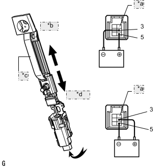
*a No Pin *b Upward *c Slider *d Downward Apply auxiliary battery voltage and check operation of the belt anchor adjuster.
OK Measurement Condition Specified Condition Auxiliary battery positive (+) → Terminal 5
Auxiliary battery negative (-) → Terminal 3
Slider moves upward Auxiliary battery positive (+) → Terminal 3
Auxiliary battery negative (-) → Terminal 5
Slider moves downward -
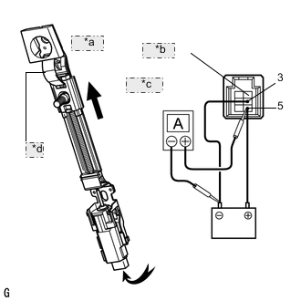
*a Upward *b No Pin *c Ammeter *d Slider Check the PTC operation inside the regulator motor.
Note
Perform this procedure with the shoulder belt anchor adjuster installed in the vehicle.
-
Disconnect the driver side shoulder belt anchor adjuster.
-
Connect the ammeter's positive (+) lead to terminal 5 of the wire harness side connector and the negative (-) lead to the auxiliary battery's negative terminal.
-
Connect the auxiliary battery's positive (+) lead to terminal 5 and negative (-) lead to terminal 3, and slide the anchor to the upward position.
-
Continue to apply voltage, and check that the current changes to less than 1 A within 6 to 46 seconds.
-
Disconnect the leads from the terminals.
-
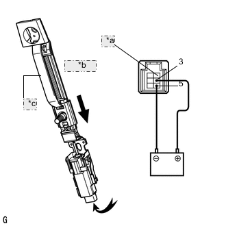
*a No Pin *b Downward *c Slider Approximately 60 seconds later, connect the auxiliary battery's positive (+) lead to terminal 3 and the negative (-) lead to terminal 5, and check that the shoulder belt anchor adjuster slides to the downward position.
If the result is not as specified replace the motor assembly.
-
-