METER / GAUGE SYSTEM Operating Light Control Rheostat does not Change Light Brightness
DESCRIPTION
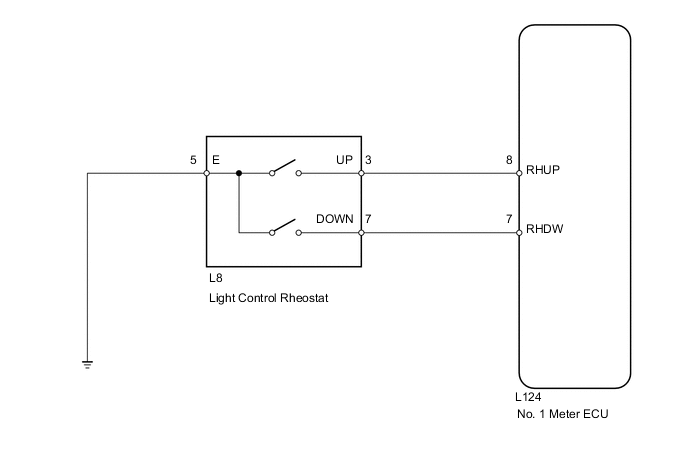
The No. 1 meter ECU receives signals for adjusting illumination on the meter of this circuit. The No. 1 meter ECU detects the illumination level selected by the user according to the switch operation.
Tech Tips
The meter illumination level can be adjusted by pushing the rheostat UP and DOWN switches.
WIRING DIAGRAM
PROCEDURE
-
READ VALUE USING INTELLIGENT TESTER (LIGHT CONTROL RHEOSTAT)
-
Connect the intelligent tester to the DLC3.
-
Turn the power switch on (IG).
-
Turn the intelligent tester on.
-
Enter the following menus: Body Electrical / Combination Meter / Data List.
-
Check the values by referring to the table below.
Combination meter Item Measurement Item / Range Normal Condition Diagnostic Note Light Control Up Switch Light control rheostat (UP) switch/ON or OFF ON: Light control rheostat (UP) switch pushed
OFF: Light control rheostat (UP) switch not pushed
- Light Control Down Switch Light control rheostat (DOWN) switch/ON or OFF ON: Light control rheostat (DOWN) switch pushed
OFF: Light control rheostat (DOWN) switch not pushed
- OK Switch condition (ON/OFF) can be switched by actual operation.
OK 
REPLACE NO. 1 METER ECU Click here
NG 
-
-
INSPECT LIGHT CONTROL RHEOSTAT
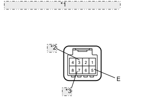
*1 Component without harness connected: (Light Control Rheostat Switch) *2 UP *3 DOWN
-
Remove the rheostat Click here.
-
Measure the resistance according to the value(s) in the table below.
Standard resistance Tester Connection Switch Condition Specified Condition 3 (UP) - 5 (E) UP switch is pushed Below 1 Ω UP switch is not pushed 10 kΩ or higher 7 (DOWN) - 5 (E) DOWN switch pushed Below 1 Ω DOWN switch is not pushed 10 kΩ or higher
NG
REPLACE LIGHT CONTROL RHEOSTAT Click here
OK
-
-
CHECK HARNESS AND CONNECTOR (NO. 1 METER ECU - LIGHT CONTROL RHEOSTAT AND BODY GROUND)
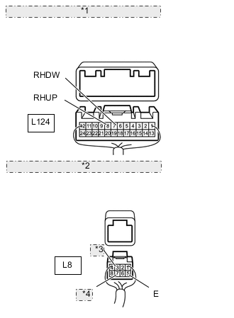
*1 Rear view of wire harness connector: (to No. 1 Meter ECU) *2 Rear view of wire harness connector: (to Light Control Rheostat) *3 UP *4 DOWN
-
Disconnect the L124 meter connector.
-
Disconnect the L8 rheostat connector.
-
Measure the resistance according to the value(s) in the table below.
Standard resistance Tester Connection Condition Specified Condition L124-8 (RHUP) - L8-3 (UP) Always Below 1 Ω L124-7 (RHDW) - L8-7 (DOWN) L8-5 (E) - Body ground L124-8 (RHUP) or L8-3 (UP) - Body ground Always 10 kΩ or higher L124-7 (RHDW) or L8-7 (DOWN) - Body ground
OK
REPLACE NO. 1 METER ECU Click here
NG
REPAIR OR REPLACE HARNESS OR CONNECTOR
-