METER / GAUGE SYSTEM Hybrid System Indicator Malfunction
DESCRIPTION
The No. 1 meter ECU receives the power meter signal from the hybrid vehicle ECU via the CAN line.
WIRING DIAGRAM
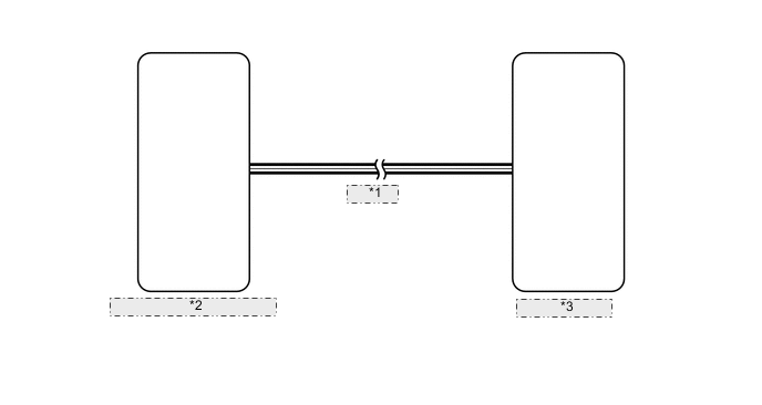
| *1 | CAN Line |
| *2 | Hybrid Vehicle Control ECU |
| *3 | No. 1 Meter ECU |
PROCEDURE
-
CHECK CAN COMMUNICATION SYSTEM
-
Check for DTC (See page [for LHD], Click here [for RHD]).
Result Result Proceed to DTC is not output A CAN communication system (for LHD) DTC is output B CAN communication system (for RHD) DTC is output C Hybrid control system is output D
B 
Go to CAN COMMUNICATION SYSTEM Click here
C
Go to CAN COMMUNICATION SYSTEM Click here
D
Go to HYBRID CONTROL SYSTEM Click here
A 
-
-
PERFORM ACTIVE TEST USING INTELLIGENT TESTER (HV SYSTEM INDICATOR)
-
Operate the intelligent tester according to the display and select "Active Test".
Combination Meter Tester Display Test Part Control Range HV System Indicator Hybrid system indicator MIN, -50, 0, 100, 200, 300, 400 or MAX (%) OK Needle indication is normal.
OK
Go to HYBRID CONTROL SYSTEM Click here
NG
REPLACE NO. 1 METER ECU Click here
-