СИСТЕМА SFI, Diagnostic DTC:P0201, P0202, P0203, P0204, P0205, P0206, P0207, P0208
| DTC Code | DTC Name |
|---|---|
| P0201 | Injector Circuit / Open - (Cylinder 1) |
| P0202 | Injector Circuit / Open - (Cylinder 2) |
| P0203 | Injector Circuit / Open - (Cylinder 3) |
| P0204 | Injector Circuit / Open - (Cylinder 4) |
| P0205 | Injector Circuit / Open - (Cylinder 5) |
| P0206 | Injector Circuit / Open - (Cylinder 6) |
| P0207 | Injector Circuit / Open - (Cylinder 7) |
| P0208 | Injector Circuit / Open - (Cylinder 8) |
DESCRIPTION
The fuel injectors are located on the intake manifold, They inject fuel into the cylinders based on the signals from the ECM.
| DTC No. | DTC Detection Condition | Trouble Area |
|---|---|---|
| P0201 P0202 P0203 P0204 P0205 P0206 P0207 P0208 |
Current is not applied to the fuel injector more than 10 times with the engine running. (1 trip detection logic) |
|
MONITOR DESCRIPTION
The ECM monitors the injection control of the fuel injector. If a malfunction is detected in the fuel injector circuit, the ECM cancels the injection control for the corresponding cylinder and turns on the MIL.
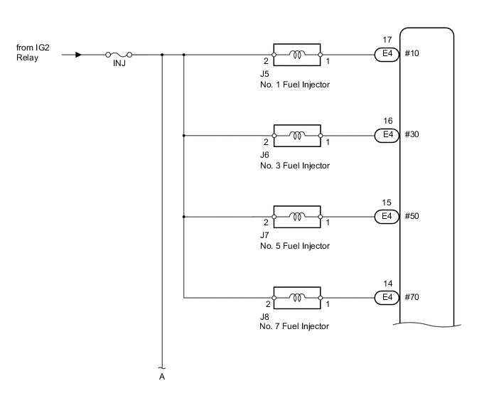
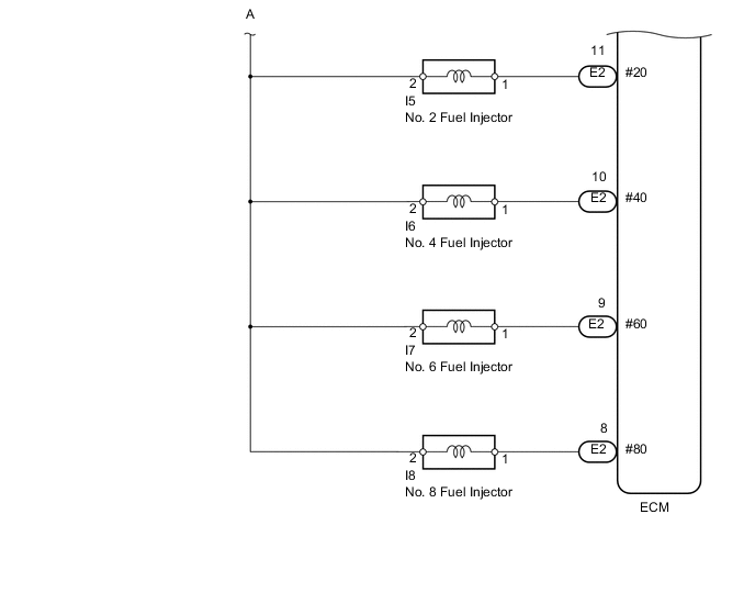
WIRING DIAGRAM
CAUTION / NOTICE / HINT
Tech Tips
Read freeze frame data using the intelligent tester. Freeze frame data records the engine condition when malfunctions are detected. When troubleshooting, freeze frame data can help determine if the vehicle was moving or stationary, if the engine was warmed up or not, if the air-fuel ratio was lean or rich, and other data from the time the malfunction occurred.
PROCEDURE
-
CHECK ANY OTHER DTCS OUTPUT (IN ADDITION TO DTC P0201, P0202, P0203, P0204, P0205, P0206, P0207 OR P0208)
-
Connect the intelligent tester to the DLC3.
-
Turn the engine switch on (IG).
-
Start the engine.
-
Turn the tester on.
-
Enter the following menus: Powertrain / Engine / DTC.
-
Read DTCs.
Result Display (DTC output) Proceed to P0201, P0202, P0203, P0204, P0205, P0206, P0207 or P0208 A P0201, P0202, P0203, P0204, P0205, P0206, P0207 or P0208 and other DTCs B
B 
GO TO DTC CHART Click here
A 
-
-
CHECK FUEL INJECTOR FOR PORT INJECTION (POWER SOURCE VOLTAGE)
-
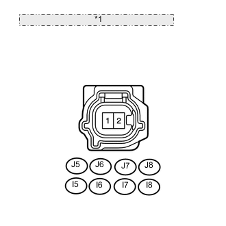
*1 Front view of wire harness connector: (to Fuel Injector) Disconnect the fuel injector connector.
-
Turn the engine switch on (IG).
-
Measure the voltage according to the value(s) in the table below.
Standard voltage Tester Connection Switch Condition Specified Condition J5-2 - Body ground Engine switch on (IG) 11 to 14 V I5-2 - Body ground Engine switch on (IG) 11 to 14 V J6-2 - Body ground Engine switch on (IG) 11 to 14 V I6-2 - Body ground Engine switch on (IG) 11 to 14 V J7-2 - Body ground Engine switch on (IG) 11 to 14 V I7-2 - Body ground Engine switch on (IG) 11 to 14 V J8-2 - Body ground Engine switch on (IG) 11 to 14 V I8-2 - Body ground Engine switch on (IG) 11 to 14 V
NG
CHECK AND REPAIR HARNESS OR CONNECTOR (INJ FUSE - INJECTOR)
OK
-
-
CHECK HARNESS AND CONNECTOR (ECM - FUEL INJECTOR)
-
Disconnect the E2 and E4 ECM connectors.
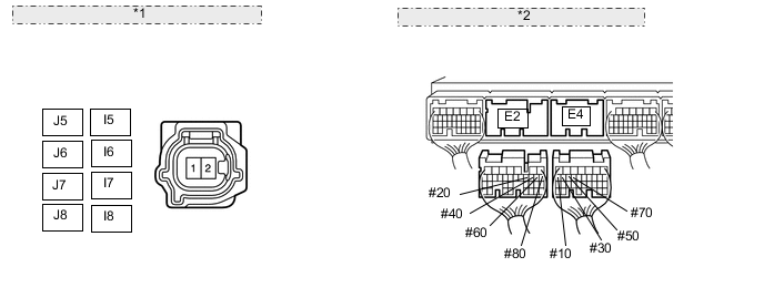
*1 Front view of wire harness connector: (to Fuel Injector for Port Injection) *2 Rear view of wire harness connector: (to ECM) -
Disconnect the fuel injector connector.
-
Measure the resistance according to the value(s) in the table below.
Standard resistance (Check for open) Tester Connection Condition Specified Condition J5-1 - E4-17 (#10) Always Below 1 Ω I5-1 - E2-11 (#20) Always Below 1 Ω J6-1 - E4-16 (#30) Always Below 1 Ω I6-1 - E2-10 (#40) Always Below 1 Ω J7-1 - E4-15 (#50) Always Below 1 Ω I7-1 - E2-9 (#60) Always Below 1 Ω J8-1 - E4-14 (#70) Always Below 1 Ω I8-1 - E2-8 (#80) Always Below 1 Ω Standard resistance (Check for short) Tester Connection Condition Specified Condition J5-1 or E4-17 (#10) - Body ground Always 10 kΩ or higher I5-1 or E2-11 (#20) - Body ground Always 10 kΩ or higher J6-1 or E4-16 (#30) - Body ground Always 10 kΩ or higher I6-1 or E2-10 (#40) - Body ground Always 10 kΩ or higher J7-1 or E4-15 (#50) - Body ground Always 10 kΩ or higher I7-1 or E2-9 (#60) - Body ground Always 10 kΩ or higher J8-1 or E4-14 (#70) - Body ground Always 10 kΩ or higher I8-1 or E2-8 (#80) - Body ground Always 10 kΩ or higher
NG
REPAIR OR REPLACE HARNESS OR CONNECTOR
OK
-
-
CHECK FUEL INJECTOR (RESISTANCE)
-
Check the fuel injector resistance Click here.
OK
REPLACE ECM Click here
NG
REPLACE FUEL INJECTOR Click here
-