SIDE STEP REASSEMBLY
CAUTION / NOTICE / HINT
Tech Tips
-
Use the same procedure for the RH and LH sides.
-
The procedure listed below is for the LH side.
-
A bolt without a torque specification is shown in the standard bolt chart Click here.
PROCEDURE
-
INSTALL STEP LIGHT ASSEMBLY (w/ Illumination)
-
INSTALL STEP LIGHT BRACKET (w/ Illumination)
-
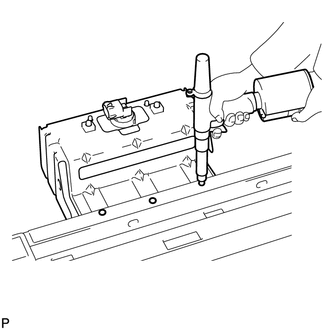
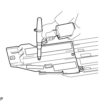
Install a nose piece to an air riveter or hand riveter.
-
Insert the mandrel part of a new rivet into the nose piece.
-
Using the riveter, install the step light bracket with the 3 rivets as shown in the illustration.
Tech Tips
If the rivet cannot be cut, pull it once and cut it.
Note
-
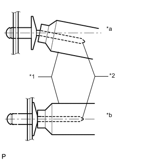
Do not pry the rivet with the riveter as this will cause damage to the riveter and mandrel.
Text in Illustration *1 Riveter *2 Mandrel *a INCORRECT *b CORRECT -
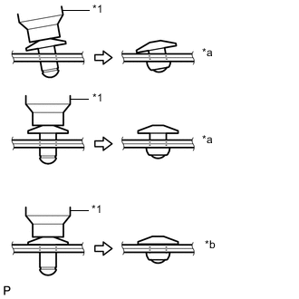
Confirm that the rivets are seated properly against the step light bracket.
-
Do not tilt the riveter when installing the rivet to the step light bracket.
-
Do not leave any space between the rivet head and step light bracket.
Text in Illustration *1 Riveter *a INCORRECT *b CORRECT -
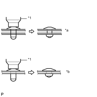
Do not leave any space between the step light bracket and step plate. Firmly hold together the 2 items while installing the rivet.
Text in Illustration *1 Riveter *a INCORRECT *b CORRECT
-
-
-
INSTALL STEP LIGHT ASSEMBLY (w/ Illumination)
-
INSTALL STEP PANEL WIRE LH (w/ Illumination)
-
INSTALL SIDE STEP BRACKET SUB-ASSEMBLY LH
-
Install a nose piece to an air riveter or hand riveter.
-
Insert the mandrel part of a new rivet into the nose piece.
-
Using the riveter, install the side step bracket with 3 rivets as shown in the illustration.
Tech Tips
If the rivet cannot be cut, pull it once and cut it.
Note
-
Do not pry the rivet with the riveter as this will cause damage to the riveter and mandrel.
Text in Illustration *1 Riveter *2 Mandrel *a INCORRECT *b CORRECT -
Confirm that the rivets are seated properly against the side step bracket.
-
Do not tilt the riveter when installing the rivet to the side step bracket.
-
Do not leave any space between the rivet head and side step bracket.
Text in Illustration *1 Riveter *a INCORRECT *b CORRECT -
Do not leave any space between the side step bracket and step plate. Firmly hold together the 2 items while installing the rivet.
Text in Illustration *1 Riveter *a INCORRECT *b CORRECT
-
-
-
INSTALL NO. 2 SIDE STEP PLATE COVER
-
Install the No. 2 side step plate cover.
-
-
INSTALL STEP PLATE COVER LH
-
Install the side step plate cover.
-
-
INSTALL STEP PLATE LH (for 5 Door)
-
Attach the 17 claws to install the step plate.
-
Install the 3 bolts and clip.
- Torque:
- 2.3 N*m { 24 kgf*cm, 20 in.*lbf }
-
-
INSTALL STEP PLATE LH (for 3 Door)
-
Attach the 14 claws to install the step plate.
-
Install the 3 bolts and clip.
- Torque:
- 2.3 N*m { 24 kgf*cm, 20 in.*lbf }
-
-
INSTALL NO. 2 ROCKER PANEL MOULDING PROTECTOR
-
Install the No. 2 rocker panel moulding protector with the 2 bolts.
- Torque:
- 3.0 N*m { 31 kgf*cm, 27 in.*lbf }
-
-
INSTALL NO. 3 SIDE STEP BRACKET LH
-
Install the No. 3 side step bracket with the 2 bolts.
- Torque:
- 6.0 N*m { 61 kgf*cm, 53 in.*lbf }
-
-
INSTALL NO. 2 SIDE STEP BRACKET LH
-
Install the No. 2 side step bracket with the 2 bolts.
- Torque:
- 6.0 N*m { 61 kgf*cm, 53 in.*lbf }
-
-
INSTALL SIDE STEP BRACKET LH
-
Install the side step bracket with the 2 bolts.
- Torque:
- 6.0 N*m { 61 kgf*cm, 53 in.*lbf }
-