STOP LIGHT SWITCH ON-VEHICLE INSPECTION
PROCEDURE
-
INSPECT STOP LIGHT SWITCH ASSEMBLY (for 5L-E)
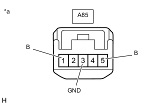
*a Front view of wire harness connector
(to Stop Light Switch Assembly)
-
Disconnect the stop light switch assembly connector.
-
Measure the resistance and voltage on the wire harness side connector according to the value(s) in the table below.
Standard Resistance If the result is not as specified, repair or replace the wire harness or connector.Tester Connection Condition Specified Condition A85-3 (GND) - Body ground Always Below 1 Ω
Standard Voltage If the result is not as specified, repair or replace the wire harness or connector.Tester Connection Condition Specified Condition A85-1 (B) - A85-3 (GND) Always 11 to 14 V A85-5 (B) - A85-3 (GND) Ignition switch on (IG) 11 to 14 V
-
Reconnect the stop light switch assembly connector.
-
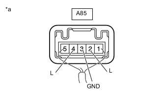
*a Component with harness connected
(Stop Light Switch Assembly)
Measure the voltage according to the value(s) in the table below.
Standard Voltage If the result is not as specified, replace the stop light switch assembly.Tester Connection Condition Specified Condition A85-2 (L) - A85-3 (GND) Ignition switch off, brake pedal not depressed Below 1 V A85-2 (L) - A85-3 (GND) Ignition switch off, brake pedal depressed 11 to 14 V A85-4 (L) - A85-3 (GND) Ignition switch on (IG), brake pedal not depressed 11 to 14 V A85-4 (L) - A85-3 (GND) Ignition switch on (IG), brake pedal depressed Below 1 V
-
-
INSPECT STOP LIGHT SWITCH ASSEMBLY (except 5L-E)
-
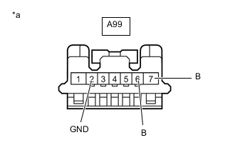
*a Front view of wire harness connector
(to Stop Light Switch Assembly)
Disconnect the stop light switch assembly connector.
-
Measure the resistance and voltage on the wire harness side connector according to the value(s) in the table below.
Standard Resistance If the result is not as specified, repair or replace the wire harness or connector.Tester Connection Condition Specified Condition A99-2 (GND) - Body ground Always Below 1 Ω
Standard Voltage If the result is not as specified, repair or replace the wire harness or connector.Tester Connection Condition Specified Condition A99-7 (B) - A99-2 (GND) Always 11 to 14 V A99-6 (B) - A99-2 (GND) Ignition switch on (IG) 11 to 14 V
-
Reconnect the stop light switch assembly connector.
-
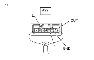
*a Component with harness connected
(Stop Light Switch Assembly)
Measure the voltage according to the value(s) in the table below.
Standard Voltage If the result is not as specified, replace the stop light switch assembly.Tester Connection Condition Specified Condition A99- 1 (OUT) - A99-2 (GND) Brake pedal not depressed 0 to 1.5 V A99-1 (OUT) - A99-2 (GND) Brake pedal depressed 7.5 to 14 V A99-3 (L) - A99-2 (GND) Brake pedal not depressed 7.5 to 14 V A99-3 (L) - A99-2 (GND) Brake pedal depressed 0 to 1.5 V A99-5 (L) - A99-2 (GND) Brake pedal not depressed 7.5 to 14 V A99-5 (L) - A99-2 (GND) Brake pedal depressed 0 to 1.5 V
-