HAZARD WARNING SWITCH INSPECTION
PROCEDURE
-
INSPECT HAZARD WARNING SIGNAL SWITCH ASSEMBLY (for 5L-E)
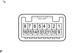
*a Component without harness connected
(Hazard Warning Signal Switch Assembly)
-
Inspect the hazard warning signal switch.
-
Measure the resistance according to the value(s) in the table below.
Standard Resistance If the result is not as specified, replace the hazard warning signal switch assembly.Tester Connection Switch Condition Specified Condition 3 - 15 Hazard warning signal switch OFF 10 kΩ or higher Hazard warning signal switch ON Below 5 Ω
-
-
Inspect the Illumination.
-
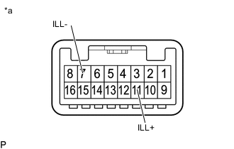
*a Component without harness connected
(Hazard Warning Signal Switch Assembly)
Apply battery voltage to the connector and check the illumination condition.
OK If the result is not as specified, replace the hazard warning signal switch assembly.Battery Connection Specified Condition Positive (+) → 11(ILL+)
Negative (-) → 7(ILL-)
Illuminates
-
-
-
INSPECT INTEGRATION CONTROL AND PANEL ASSEMBLY (except 5L-E)
-
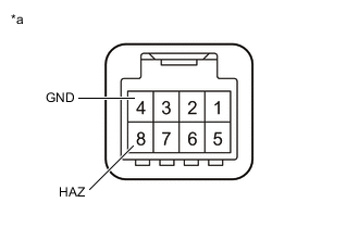
*a Component without harness connected
(Integration Control and Panel Assembly)
Inspect the hazard warning signal switch.
-
Measure the resistance according to the value(s) in the table below.
Standard Resistance If the result is not as specified, replace the integration control and panel assembly.Tester Connection Switch Condition Specified Condition 8(HAZ) - 4(GND) Hazard warning signal switch OFF 10 kΩ or higher Hazard warning signal switch ON Below 1 Ω
-
-
Inspect the Illumination.
-
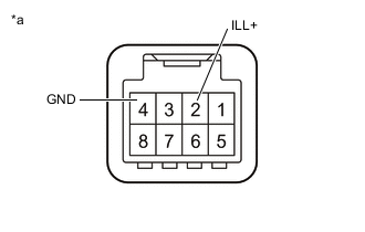
*a Component without harness connected
(Integration Control and Panel Assembly)
Apply battery voltage to the connector and check the illumination condition.
OK If the result is not as specified, replace the integration control and panel assembly.Battery Connection Specified Condition Positive (+) → 2(ILL+)
Negative (-) → 4(GND)
Illuminates
-
-