HAZARD WARNING SWITCH INSPECTION
CAUTION / NOTICE / HINT
Tech Tips
-
Use the same procedure for RHD and LHD vehicles.
-
The procedure listed below is for LHD vehicles.
PROCEDURE
-
INSPECT HAZARD WARNING SIGNAL SWITCH ASSEMBLY (w/o Display)
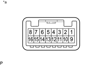
Text in Illustration *a Component without harness connected
(Hazard Warning Signal Switch Assembly)
-
Check the resistance.
-
Measure the resistance according to the value(s) in the table below.
Standard Resistance Tester Connection Switch Condition Specified Condition 3 - 16 Hazard warning signal switch off 10 kΩ or higher Hazard warning signal switch on Below 1 Ω If the result is not as specified, there may be a malfunction in the hazard warning signal switch assembly.
-
-
Illumination inspection.
-
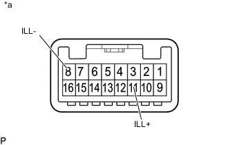
Text in Illustration *a Component without harness connected
(Hazard Warning Signal Switch Assembly)
Apply battery voltage to the connector and check the illumination condition.
OK Measurement Condition Specified Condition Battery positive (+) → Terminal 11 (ILL+)
Battery negative (-) → Terminal 8 (ILL-)
Illuminates If the result is not as specified, there may be a malfunction in the hazard warning signal switch assembly.
-
-
-
INSPECT HAZARD WARNING SIGNAL SWITCH ASSEMBLY (w/ Display)
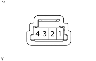
Text in Illustration *a Component without harness connected
(Hazard Warning Signal Switch Assembly)
-
Check the resistance.
-
Measure the resistance according to the value(s) in the table below.
Standard Resistance Tester Connection Switch Condition Specified Condition 4 - 1 Hazard warning signal switch off 10 kΩ or higher Hazard warning signal switch on Below 1 Ω If the result is not as specified, there may be a malfunction in the hazard warning signal switch assembly.
-
-
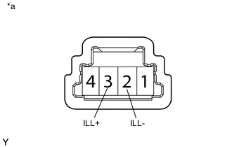
Text in Illustration *a Component without harness connected
(Hazard Warning Signal Switch Assembly)
Illumination inspection.
-
Apply battery voltage to the connector and check the illumination condition.
OK Measurement Condition Specified Condition Battery positive (+) → Terminal 3 (ILL+)
Battery negative (-) → Terminal 2 (ILL-)
Illuminates If the result is not as specified, there may be a malfunction in the hazard warning signal switch assembly.
-
-