LIGHTING SYSTEM(for LED Headlight) Clearance Light/Daytime Running Light Circuit
DESCRIPTION
-
When the main body ECU (multiplex network body ECU) receives the light control switch position signal, it sends an illumination request signal to the No. 1 headlight ECU sub-assembly and illuminates the clearance lights.
Clearance light function:
-
When the operation conditions of the daytime running lights are met, the main body ECU (multiplex network body ECU) sends an illumination request signal to the No. 1 headlight ECU sub-assembly and illuminates the daytime running lights.
Daytime running light function:
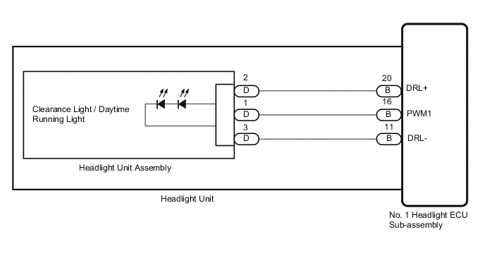
WIRING DIAGRAM
CAUTION / NOTICE / HINT
Note
-
Before troubleshooting, make sure that the customize setting "DRL Function" is set to "ON".
-
If the No. 1 headlight ECU sub-assembly LH has been replaced, it is necessary to synchronize the vehicle information and initialize the No. 1 headlight ECU sub-assembly LH.
PROCEDURE
-
PERFORM ACTIVE TEST USING GTS
-
Using the GTS, perform the Active Test.
AFS Tester Display Measurement Item Control Range Diagnostic Note Clearance Light Clearance lights OFF or ON - Daytime Running Light Daytime running lights OFF or ON - OK Clearance lights and daytime running lights illuminate. Result Result Proceed to OK A NG (LH side clearance lights and daytime running lights does not illuminate.) B NG (RH side clearance lights and daytime running lights does not illuminate.) C
A 
PROCEED TO NEXT SUSPECTED AREA SHOWN IN PROBLEM SYMPTOMS TABLE Click here
C 
CHECK HEADLIGHT UNIT RH Click here
B 
-
-
CHECK HEADLIGHT UNIT LH
-
Interchange the headlight unit LH with RH and connect the connectors to them.
-
Check that the clearance light LH and daytime running light LH operate normally.
AFS Tester Display Measurement Item Control Range Diagnostic Note Clearance Light Clearance lights OFF or ON - Daytime Running Light Daytime running lights OFF or ON - OK Clearance light LH and daytime running light LH illuminate. Result Proceed to OK NG
NG
REPLACE NO. 1 HEADLIGHT ECU SUB-ASSEMBLY LH Click here
OK
-
-
CHECK HEADLIGHT UNIT LH
-
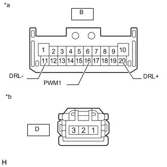
*a Front view of wire harness connector
(to No. 1 Headlight ECU Sub-assembly LH)
*b Front view of wire harness connector
(to Headlight Unit Assembly LH)
Remove the headlight unit assembly LH.
-
Remove the headlight unit LH.
-
Measure the resistance according to the value(s) in the table below.
Standard Resistance Tester Connection Condition Specified Condition B-20 (DRL+) - D-2 Always Below 1 Ω B-16 (PWM1) - D-1 Always Below 1 Ω B-11 (DRL-) - D-3 Always Below 1 Ω Result Proceed to OK NG
OK
REPLACE HEADLIGHT UNIT ASSEMBLY LH Click here
NG
REPLACE HEADLIGHT UNIT LH Click here
-
-
CHECK HEADLIGHT UNIT RH
-
Interchange the headlight unit RH with LH and connect the connectors to them.
-
Check that the clearance light RH and daytime running light RH operate normally.
AFS Tester Display Measurement Item Control Range Diagnostic Note Clearance Light Clearance lights OFF or ON - Daytime Running Light Daytime running lights OFF or ON - OK Clearance light RH and daytime running light RH illuminate. Result Proceed to OK NG
NG
REPLACE NO. 1 HEADLIGHT ECU SUB-ASSEMBLY RH Click here
OK
-
-
CHECK HEADLIGHT UNIT RH
-
*a Front view of wire harness connector
(to No. 1 Headlight ECU Sub-assembly RH)
*b Front view of wire harness connector
(to Headlight Unit Assembly RH)
Remove the headlight unit assembly RH.
-
Remove the headlight unit RH.
-
Measure the resistance according to the value(s) in the table below.
Standard Resistance Tester Connection Condition Specified Condition B-20 (DRL+) - D-2 Always Below 1 Ω B-16 (PWM1) - D-1 Always Below 1 Ω B-11 (DRL-) - D-3 Always Below 1 Ω Result Proceed to OK NG
OK
REPLACE HEADLIGHT UNIT ASSEMBLY RH Click here
NG
REPLACE HEADLIGHT UNIT RH Click here
-