LIGHTING SYSTEM(for LED Headlight) Turn Signal Switch Circuit
DESCRIPTION
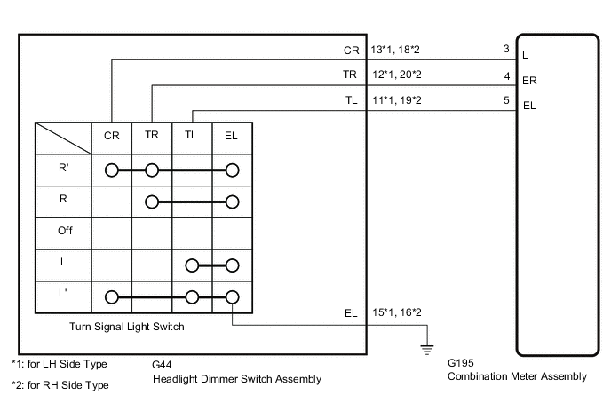
The combination meter assembly receives the turn signal switch information and controls the turn signal lights.
WIRING DIAGRAM
CAUTION / NOTICE / HINT
Note
When replacing the combination meter assembly, always replace it with a new one. If a combination meter assembly which was installed to another vehicle is used, the information stored in it will not
PROCEDURE
-
READ VALUE USING GTS
-
Using the GTS, read the Data List.
Combination Meter Tester Display Measurement Item / Range Normal Condition Diagnostic Note Turn Signal Switch (Right) Turn signal switch (right) signal / OFF or ON OFF: Turn signal switch not in right turn position
ON: Turn signal switch in right turn position
- Turn Signal Switch (Left) Turn signal switch (left) signal / OFF or ON OFF: Turn signal switch not in left turn position
ON: Turn signal switch in left turn position
- Turn Switch Signal (Full Turn) Turn signal switch signal / OFF or ON OFF: Turn signal switch off
ON: Turn signal switch on (Full Turn)
Displays for both right and left turns. OK Normal condition listed above are displayed. Result Proceed to OK NG
OK 
PROCEED TO NEXT SUSPECTED AREA SHOWN IN PROBLEM SYMPTOMS TABLE Click here
NG 
-
-
INSPECT HEADLIGHT DIMMER SWITCH ASSEMBLY
-
Remove the headlight dimmer switch assembly.
-
Inspect the headlight dimmer switch assembly.
Result Proceed to OK NG
NG
REPLACE HEADLIGHT DIMMER SWITCH ASSEMBLY Click here
OK
-
-
CHECK HARNESS AND CONNECTOR (HEADLIGHT DIMMER SWITCH ASSEMBLY - COMBINATION METER ASSEMBLY AND BODY GROUND)
-
Disconnect the G44 headlight dimmer switch assembly connector.
-
Disconnect the G195 combination meter assembly connector.
-
Measure the resistance according to the value(s) in the table below.
Standard Resistance for LH Side Type Tester Connection Condition Specified Condition G44-13 (CR) - G195-3 (L) Always Below 1 Ω G44-12 (TR) - G195-4 (ER) Always Below 1 Ω G44-11 (TL) - G195-5 (EL) Always Below 1 Ω G44-15 (EL) - Body ground Always Below 1 Ω G44-13 (CR) or G195-3 (L) - Body ground Always 10 kΩ or higher G44-12 (TR) or G195-4 (ER) - Body ground Always 10 kΩ or higher G44-11 (TL) or G195-5 (EL) - Body ground Always 10 kΩ or higher for RH Side Type Tester Connection Condition Specified Condition G44-18 (CR) - G195-3 (L) Always Below 1 Ω G44-20 (TR) - G195-4 (ER) Always Below 1 Ω G44-19 (TL) - G195-5 (EL) Always Below 1 Ω G44-16 (EL) - Body ground Always Below 1 Ω G44-18 (CR) or G195-3 (L) - Body ground Always 10 kΩ or higher G44-20 (TR) or G195-4 (ER) - Body ground Always 10 kΩ or higher G44-19 (TL) or G195-5 (EL) - Body ground Always 10 kΩ or higher Result Proceed to OK NG
OK
REPLACE COMBINATION METER ASSEMBLY Click here
NG
REPAIR OR REPLACE HARNESS OR CONNECTOR
-