LIGHTING SYSTEM(for LED Headlight), Diagnostic DTC:B2424, B2425
| DTC Code | DTC Name |
|---|---|
| B2424 | Headlight Leveling Motor LH Communication Malfunction |
| B2425 | Headlight Beam Level Control Motor RH Lost Communication |
DESCRIPTION
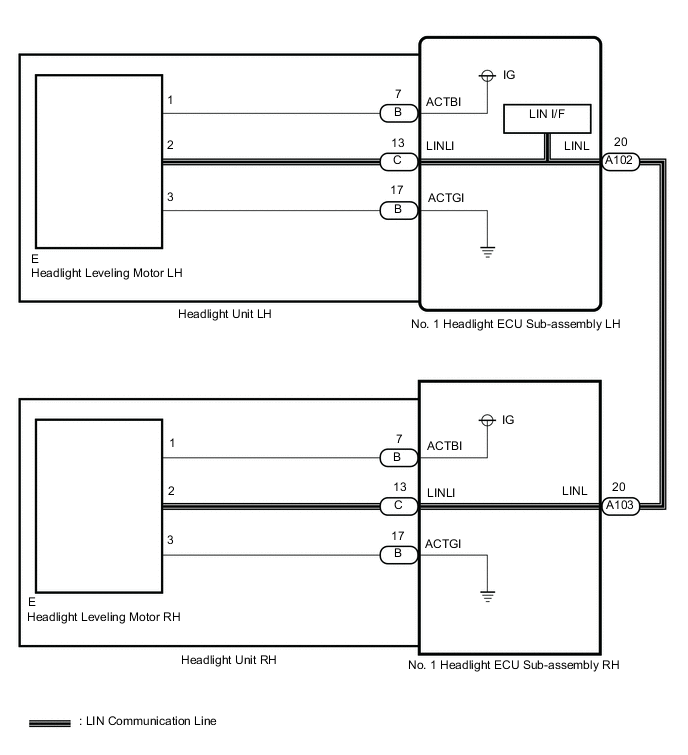
The No. 1 headlight ECU sub-assembly receives a signal from each headlight leveling motor using LIN communication.
| DTC No. | Detection Item | DTC Detection Condition | Trouble Area | DTC Output from | Note |
|---|---|---|---|---|---|
| B2424 | Headlight Leveling Motor LH Communication Malfunction | Either condition is met:
|
|
No. 1 headlight ECU sub-assembly LH | - |
| B2425 | Headlight Beam Level Control Motor RH Lost Communication | Either condition is met:
|
|
No. 1 headlight ECU sub-assembly LH | - |
WIRING DIAGRAM
CAUTION / NOTICE / HINT
Note
If the No. 1 headlight ECU sub-assembly LH has been replaced, it is necessary to synchronize the vehicle information and initialize the No. 1 headlight ECU sub-assembly LH.
PROCEDURE
-
CHECK FOR DTC
-
Clear the DTCs.
-
Turn the ignition switch to ON.
-
Check for DTCs.
OK DTC B2424 and B2425 are not output. Result Result Proceed to OK A NG (DTC B2424 and B2425 are output) B NG (DTC B2424 is output) C NG (DTC B2425 is output) D
A 
USE SIMULATION METHOD TO CHECK Click here
C 
CHECK HEADLIGHT UNIT LH Click here
D
CHECK HARNESS AND CONNECTOR (NO. 1 HEADLIGHT ECU SUB-ASSEMBLY LH - NO. 1 HEADLIGHT ECU SUB-ASSEMBLY RH) Click here
B 
-
-
CHECK HEADLIGHT ASSEMBLY RH
-
Disconnect the A103 No. 1 headlight ECU sub-assembly RH connector.
-
Clear the DTCs.
-
Turn the ignition switch to ON.
-
Check for DTCs.
Result Result Proceed to Only DTC B2425 is output A DTC B2424 and B2425 are output B
B
CHECK HARNESS AND CONNECTOR (NO. 1 HEADLIGHT ECU SUB-ASSEMBLY LH - NO. 1 HEADLIGHT ECU SUB-ASSEMBLY RH) Click here
A
-
-
CHECK NO. 1 HEADLIGHT ECU SUB-ASSEMBLY RH
-
Remove the No. 1 headlight ECU sub-assembly RH.
-
Connect the A103 No. 1 headlight ECU sub-assembly RH connector.
-
Clear the DTCs.
-
Turn the ignition switch to ON.
-
Check for DTCs.
Result Result Proceed to Only DTC B2425 is output A DTC B2424 and B2425 are output B
B
REPLACE NO. 1 HEADLIGHT ECU SUB-ASSEMBLY RH Click here
A
-
-
CHECK HEADLIGHT LEVELING MOTOR RH
-
Disconnect the headlight leveling motor RH connector.
-
Connect the No. 1 headlight ECU sub-assembly RH connectors.
-
Clear the DTCs.
-
Turn the ignition switch to ON.
-
Check for DTCs.
Result Result Proceed to Only DTC B2425 is output A DTC B2424 and B2425 are output B
A
REPLACE HEADLIGHT LEVELING MOTOR RH Click here
B
REPLACE HEADLIGHT UNIT RH Click here
-
-
CHECK HARNESS AND CONNECTOR (NO. 1 HEADLIGHT ECU SUB-ASSEMBLY LH - NO. 1 HEADLIGHT ECU SUB-ASSEMBLY RH)
-
Disconnect the A102 No. 1 headlight ECU sub-assembly LH connector.
-
Disconnect the A103 No. 1 headlight ECU sub-assembly RH connector.
-
Measure the resistance according to the value(s) in the table below.
Standard Resistance Tester Connection Condition Specified Condition A102-20 (LINL) or A103-20 (LINL) - Body ground Always 10 kΩ or higher Result Proceed to OK NG
NG
REPAIR OR REPLACE HARNESS OR CONNECTOR
OK
-
-
CHECK NO. 1 HEADLIGHT ECU SUB-ASSEMBLY LH
-
Remove the No. 1 headlight ECU sub-assembly LH.
-
Connect the A102 No. 1 headlight ECU sub-assembly LH connector.
-
Clear the DTCs.
-
Turn the ignition switch to ON.
-
Check for DTCs.
Result Result Proceed to Only DTC B2424 is output A DTC B2424 and B2425 are output B
B
REPLACE NO. 1 HEADLIGHT ECU SUB-ASSEMBLY LH Click here
A
-
-
CHECK HEADLIGHT LEVELING MOTOR LH
-
Disconnect the headlight leveling motor LH connector.
-
Connect the No. 1 headlight ECU sub-assembly LH connectors.
-
Clear the DTCs.
-
Turn the ignition switch to ON.
-
Check for DTCs.
Result Result Proceed to Only DTC B2424 is output A DTC B2424 and B2425 are output B
A
REPLACE HEADLIGHT LEVELING MOTOR LH Click here
B
REPLACE HEADLIGHT UNIT LH Click here
-
-
CHECK HEADLIGHT UNIT LH
-
Remove the headlight unit LH.
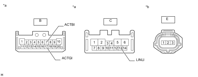
*a Front view of wire harness connector
(to No. 1 Headlight ECU Sub-assembly LH)
*b Front view of wire harness connector
(to Headlight Unit Assembly LH)
-
Measure the resistance according to the value(s) in the table below.
Standard Resistance Tester Connection Condition Specified Condition B-7 (ACTBI) - E-1 Always Below 1 Ω B-17 (ACTGI) - E-3 Always Below 1 Ω C-13 (LINLI) - E-2 Always Below 1 Ω Result Proceed to OK NG
NG
REPLACE HEADLIGHT UNIT LH Click here
OK
-
-
CHECK NO. 1 HEADLIGHT ECU SUB-ASSEMBLY LH
-
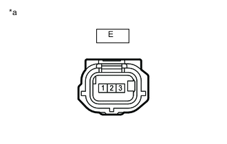
*a Front view of wire harness connector
(to Headlight Leveling Motor LH)
Disconnect the headlight leveling motor LH connector.
-
Connect the No. 1 headlight ECU sub-assembly LH connectors.
-
Measure the voltage according to the value(s) in the table below.
Standard Voltage Tester Connection Switch Condition Specified Condition E-1 - E-3 Ignition switch ON 11 to 14 V Ignition switch off Below 1 V Result Proceed to OK NG
NG
REPLACE NO. 1 HEADLIGHT ECU SUB-ASSEMBLY LH Click here
OK
-
-
CHECK NO. 1 HEADLIGHT ECU SUB-ASSEMBLY LH
-
Remove the No. 1 headlight ECU sub-assembly LH as a unit with the connectors still connected.
-
Disconnect the A103 No. 1 headlight ECU sub-assembly RH connector.
-
Measure the resistance according to the value(s) in the table below.
Standard Resistance Tester Connection Condition Specified Condition C-13 (LINLI) - A103-20 (LINL) Always Below 1 Ω Result Proceed to OK NG
OK
REPLACE HEADLIGHT LEVELING MOTOR LH Click here
NG
REPLACE NO. 1 HEADLIGHT ECU SUB-ASSEMBLY LH Click here
-
-
CHECK HARNESS AND CONNECTOR (NO. 1 HEADLIGHT ECU SUB-ASSEMBLY LH - NO. 1 HEADLIGHT ECU SUB-ASSEMBLY RH)
-
Disconnect the A102 No. 1 headlight ECU sub-assembly LH connector.
-
Disconnect the A103 No. 1 headlight ECU sub-assembly RH connector.
-
Measure the resistance according to the value(s) in the table below.
Standard Resistance Tester Connection Condition Specified Condition A102-20 (LINL) - A103-20 (LINL) Always Below 1 Ω Result Proceed to OK NG
NG
REPAIR OR REPLACE HARNESS OR CONNECTOR
OK
-
-
CHECK HEADLIGHT UNIT RH
-
Remove the headlight unit RH.
*a Front view of wire harness connector
(to No. 1 Headlight ECU Sub-assembly RH)
*b Front view of wire harness connector
(to Headlight Unit Assembly RH)
-
Measure the resistance according to the value(s) in the table below.
Standard Resistance Tester Connection Condition Specified Condition B-7 (ACTBI) - E-1 Always Below 1 Ω B-17 (ACTGI) - E-3 Always Below 1 Ω B-13 (LINLI) - E-2 Always Below 1 Ω Result Proceed to OK NG
NG
REPLACE HEADLIGHT UNIT RH Click here
OK
-
-
CHECK NO. 1 HEADLIGHT ECU SUB-ASSEMBLY RH
-
*a Front view of wire harness connector
(to Headlight Leveling Motor RH)
Disconnect the headlight leveling motor RH connector.
-
Connect the No. 1 headlight ECU sub-assembly RH connectors.
-
Measure the voltage according to the value(s) in the table below.
Standard Voltage Tester Connection Switch Condition Specified Condition E-1 - E-3 Ignition switch ON 11 to 14 V Ignition switch off Below 1 V Result Proceed to OK NG
NG
REPLACE NO. 1 HEADLIGHT ECU SUB-ASSEMBLY RH Click here
OK
-
-
CHECK NO. 1 HEADLIGHT ECU SUB-ASSEMBLY RH
-
Remove the No. 1 headlight ECU sub-assembly RH as a unit with the connectors still connected.
-
Disconnect the A102 No. 1 headlight ECU sub-assembly LH connector.
-
Measure the resistance according to the value(s) in the table below.
Standard Resistance Tester Connection Condition Specified Condition C-13 (LINLI) - A102-20 (LINL) Always Below 1 Ω Result Proceed to OK NG
OK
REPLACE HEADLIGHT LEVELING MOTOR RH Click here
NG
REPLACE NO. 1 HEADLIGHT ECU SUB-ASSEMBLY RH Click here
-