LIGHTING SYSTEM(for LED Headlight), Diagnostic DTC:U0242
| DTC Code | DTC Name |
|---|---|
| U0242 | Lost Communication With Headlamp Control Module "B" |
DESCRIPTION
| DTC No. | Detection Item | DTC Detection Condition | Trouble Area | DTC Output from | Note |
|---|---|---|---|---|---|
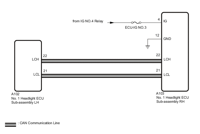
| U0242 | Lost Communication With Headlamp Control Module "B" | The No. 1 headlight ECU sub-assembly LH does not receive data from the No. 1 headlight ECU sub-assembly RH for approximately 10 seconds or more. |
|
No. 1 headlight ECU sub-assembly LH | - |
WIRING DIAGRAM
CAUTION / NOTICE / HINT
Note
-
Inspect the fuse for circuits related to this system before performing the follow ingprocedure.
-
If the No. 1 headlight ECU sub-assembly LH has been replaced, it is necessary to synchronize the vehicle information and initialize the No. 1 headlight ECU sub-assembly LH.
PROCEDURE
-
CHECK DTC
-
Clear the DTCs.
-
Turn the ignition switch to ON and wait for at least 10 seconds or more.
-
Check for DTCs.
OK DTC U0242 is not output. Result Proceed to OK NG
OK 
USE SIMULATION METHOD TO CHECK
NG 
-
-
CHECK HARNESS AND CONNECTOR (NO. 1 HEADLIGHT ECU SUB-ASSEMBLY RH - BATTERY AND BODY GROUND)
-
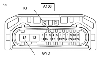
*a Front view of wire harness connector
(to No. 1 Headlight ECU Sub-assembly RH)
Disconnect the No. 1 headlight ECU sub-assembly RH connector.
-
Measure the voltage according to the value(s) in the table below.
Standard Voltage Tester Connection Switch Condition Specified Condition A103-4 (IG) - Body ground Ignition switch ON 11 to 14 V -
Measure the resistance according to the value(s) in the table below.
Standard Resistance Tester Connection Condition Specified Condition A103-12 (GND) - Body ground Always Below 1 Ω Result Proceed to OK NG
NG
REPAIR OR REPLACE HARNESS OR CONNECTOR
OK
-
-
CHECK FOR CAN BUS WIRE (NO. 1 HEADLIGHT ECU SUB-ASSEMBLY LH CAN MAIN WIRE)
-

*a Front view of wire harness connector
(to No. 1 Headlight ECU Sub-assembly LH)
Disconnect the cable from the negative (-) battery terminal.
-
Disconnect the No. 1 headlight ECU sub-assembly LH connector.
-
Measure the resistance according to the value(s) in the table below.
Standard Resistance Tester Connection Condition Specified Condition A102-22 (LCH) - A102-21 (LCL) Cable disconnected from negative (-) battery terminal 108 to 132 Ω A102-22 (LCH) - +B Cable disconnected from negative (-) battery terminal 6 kΩ or higher A102-21 (LCL) - +B Cable disconnected from negative (-) battery terminal 200 Ω or higher A102-22 (LCH) - GND Cable disconnected from negative (-) battery terminal 200 Ω or higher A102-21 (LCL) - GND Cable disconnected from negative (-) battery terminal 200 Ω or higher Result Proceed to OK NG
OK
REPLACE NO. 1 HEADLIGHT ECU SUB-ASSEMBLY LH Click here
NG
-
-
CHECK FOR CAN BUS WIRE (NO. 1 HEADLIGHT ECU SUB-ASSEMBLY RH CAN MAIN WIRE)
-
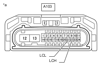
*a Front view of wire harness connector
(to No. 1 Headlight ECU Sub-assembly RH)
Disconnect the cable from the negative (-) battery terminal.
-
Disconnect the No. 1 headlight ECU sub-assembly RH connector.
-
Measure the resistance according to the value(s) in the table below.
Standard Resistance Tester Connection Condition Specified Condition A103-22 (LCH) - A103-21 (LCL) Cable disconnected from negative (-) battery terminal 108 to 132 Ω A103-22 (LCH) - +B Cable disconnected from negative (-) battery terminal 6 kΩ or higher A103-21 (LCL) - +B Cable disconnected from negative (-) battery terminal 200 Ω or higher A103-22 (LCH) - GND Cable disconnected from negative (-) battery terminal 200 Ω or higher A103-21 (LCL) - GND Cable disconnected from negative (-) battery terminal 200 Ω or higher Result Proceed to OK NG
OK
REPLACE NO. 1 HEADLIGHT ECU SUB-ASSEMBLY RH Click here
NG
REPAIR OR REPLACE CAN MAIN WIRE OR CONNECTOR
-