LIGHTING SYSTEM(for LED Headlight) TERMINALS OF ECU
-
CHECK DRIVER SIDE JUNCTION BLOCK ASSEMBLY AND MAIN BODY ECU (MULTIPLEX NETWORK BODY ECU)
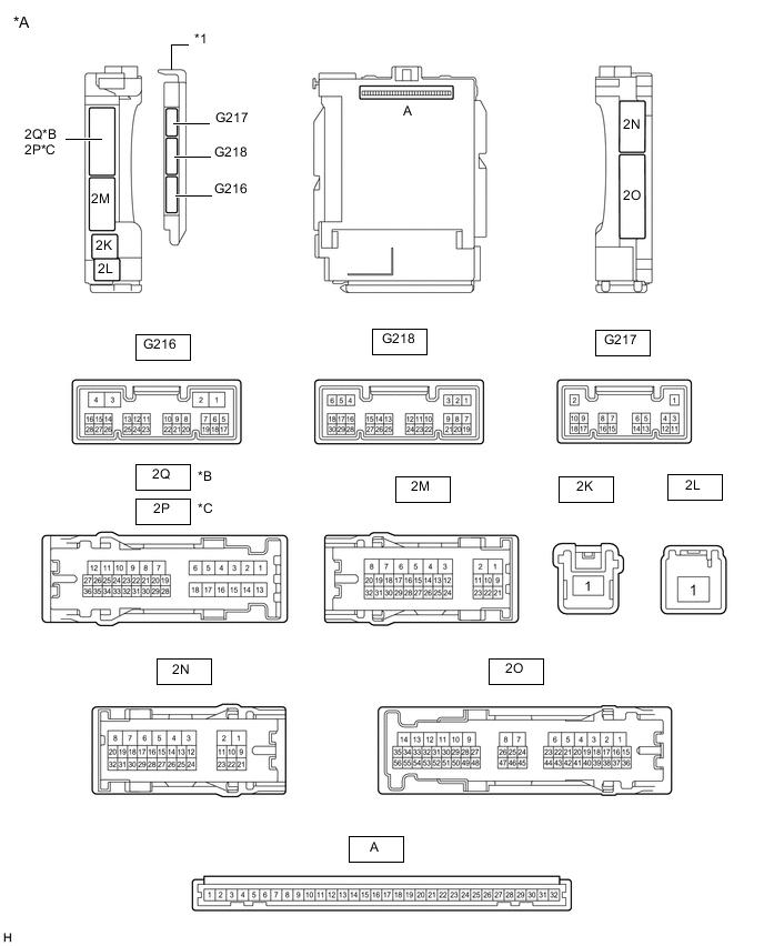
*A Main Body ECU (Multiplex Network Body ECU) with 3 connectors *B for LHD *C for RHD - - *1 Main Body ECU (Multiplex Network Body ECU) - - 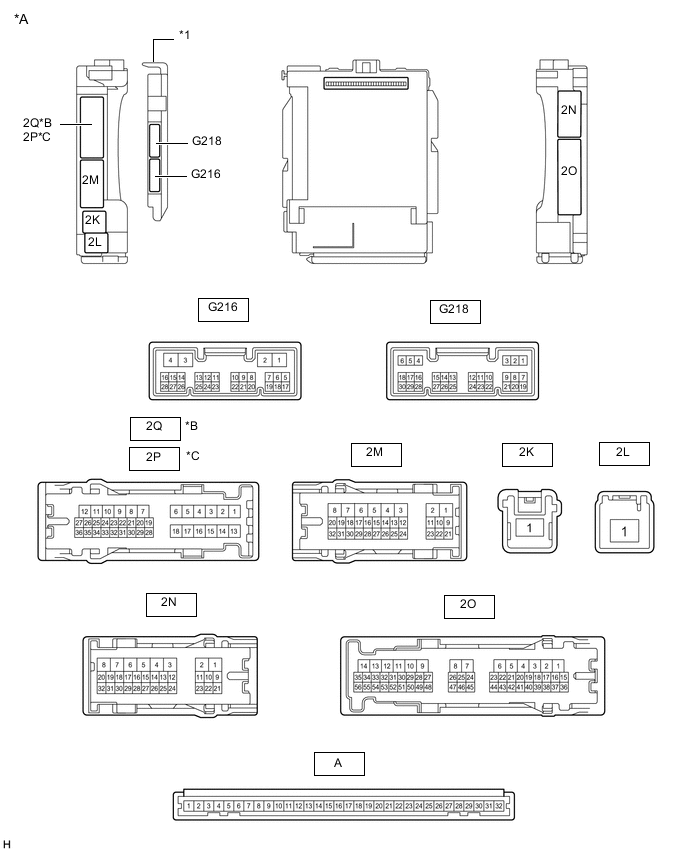
*A Main Body ECU (Multiplex Network Body ECU) with 2 connectors *B for LHD *C for RHD - - *1 Main Body ECU (Multiplex Network Body ECU) - -
-
Remove the main body ECU (multiplex network body ECU) from the driver side junction block assembly.
-
Connect the driver side junction block assembly connectors.
-
Measure the voltage and resistance according to the value(s) in the table below.
Terminal No. (Symbol) Wiring Color Terminal Description Condition Specified Condition A-32 (IG) - Body ground Note - Body ground Ignition power supply Ignition switch ON 11 to 14 V Ignition switch off Below 1 V A-31 (BECU) - Body ground Note - Body ground Battery power supply Always 11 to 14 V A-30 (ACC) - Body ground Note - Body ground ACC power supply Ignition switch ACC 11 to 14 V Ignition switch off Below 1 V A-11 (GND1) - Body ground Note - Body ground Ground Always Below 1 Ω -
Install the main body ECU (multiplex network body ECU).
-
Measure the voltage and pulse according to the value(s) in the table below.
Terminal No. (Symbol) Wiring Color Terminal Description Condition Specified Condition G216-23 (AHBI) - Body ground*5 P - Body ground Auto high beam switch signal input Auto high beam switch on Below 1 V Auto high beam switch off 11 to 14 V G218-1 (DIM) - Body ground P - Body ground H-LP HI relay drive output Ignition switch ON Below 1 V Ignition switch off 11 to 14 V G218-8 (A) - Body ground W - Body ground Light control switch Auto position signal input Light control switch in Auto position Below 1 V Light control switch not in Auto position 11 to 14 V G218-10 (HF) - Body ground V - Body ground Headlight dimmer switch high flash position signal input Headlight dimmer switch in high flash position Below 1 V Headlight dimmer switch not in high flash position 11 to 14 V G218-12 (HEAD) - Body ground SB - Body ground Light control switch head position signal input Light control switch in head position Below 1 V Light control switch not in head position 11 to 14 V G218-19 (CLTB) - G218-21 (CLTE) P - L Automatic light control sensor power supply output Ignition switch off Below 1 V Ignition switch ON 11 to 14 V G218-20 (CLTS) - Body ground R - Body ground Automatic light control sensor signal input Ignition switch off Below 1 V Automatic light control system operating Pulse generation
(See waveform 1)
G218-22 (TAIL) - Body ground W - Body ground Light control switch tail position signal input Light control switch in tail or head position Below 1 V Light control switch not in tail or head position 11 to 14 V G218-23 (RFOG) - Body ground*1 SB - Body ground Fog light switch rear position input Fog light switch in rear position Below 1 V Fog light switch off 11 to 14 V G218-24 (HU) - Body ground LG - Body ground Headlight dimmer switch high position signal input Headlight dimmer switch in high flash position Below 1 V Headlight dimmer switch not in high flash position 11 to 14 V G218-26 (FFOG) - Body ground*2 G - Body ground Fog light switch front position input Fog light switch in front position Below 1 V Fog light switch off 11 to 14 V 2Q-31 - Body ground*3 LG - Body ground Taillight drive output Light control switch in tail or head position Below 1 V Light control switch off 11 to 14 V 2N-9 - Body ground*4 LG - Body ground Taillight drive output Light control switch in tail or head position Below 1 V Light control switch off 11 to 14 V 2M-17 (HRLY) - Body ground GR - Body ground H-LP LO relay drive output Ignition switch ON Below 1 V Ignition switch off 11 to 14 V 2Q-11 - Body ground*1, *3 G - Body ground Rear fog light drive output Light control switch in tail or head position, fog light switch off Below 1 V Light control switch in tail or head position, fog light switch in rear position 11 to 14 V 2P-11 - Body ground*1, *4 G - Body ground Rear fog light drive output Light control switch in tail or head position, fog light switch off Below 1 V Light control switch in tail or head position, fog light switch in rear position 11 to 14 V 2M-19 - Body ground*2 W - Body ground Front fog light drive output Light control switch in tail or head position, fog light switch off Below 1 V Light control switch in tail or head position, fog light switch in front position 11 to 14 V *1: w/ Rear Fog Light
*2: w/ Front Fog Light
*3: for LHD
*4: for RHD
*5: w/ Automatic High Beam System
-
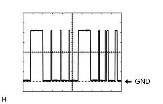
Waveform 1
Item Content Terminal No. (Symbol) G218-20 (CLTS) - Body ground Tool Setting 2 V/DIV., 10 ms./DIV. Condition Automatic light control system operating Tech Tips
The communication waveform changes according to the surrounding brightness.
-
-
CHECK NO. 1 HEADLIGHT ECU SUB-ASSEMBLY LH

-
Disconnect the A102 No. 1 headlight ECU sub-assembly LH connector.
-
Measure the resistance and voltage according to the value(s) in the table below.
Terminal No. (Symbol) Wiring Color Terminal Description Condition Specified Condition A102-4 (IG) - Body ground GR - Body ground Ignition power supply Ignition switch off Below 1 V Ignition switch ON 11 to 14 V A102-13 (ECUB) - Body ground R - Body ground Power supply Ignition switch off Below 1 V Ignition switch ON 11 to 14 V A102-12 (GND) - Body ground W-B - Body ground Ground Always Below 1 Ω -
Reconnect the A102 No. 1 headlight ECU sub-assembly LH connector.
Tech Tips
-
Since the A102 No. 1 headlight ECU sub-assembly LH connector is a waterproof type connector, the voltage and pulses cannot be checked directly. The values listed are for reference only.
-
Since the B and C No. 1 headlight ECU sub-assembly LH connector is connected inside the headlight assembly, the voltage and pulses cannot be checked directly. The values listed are for reference only.
-
-
Measure the voltage and check of pulses according to the value(s) in the table below.
Terminal No. (Symbol) Wiring Color Terminal Description Condition Specified Condition A102-11 (TNS) - Body ground V - Body ground Left turn signal light signal input Ignition switch ON, left turn signal light off Below 1 V Ignition switch ON, left turn signal light blinking 11 to 14 V ←→ Below 1 V A102-16 (SBR) - A102-15 (SGR)* R-G - W Rear height control sensor power supply Ignition switch off Below 1 V Ignition switch ON 4.5 to 5.5 V A102-17 (SHRL) - A102-15 (SGR)* B-R - W Rear height control sensor signal input Ignition switch ON, vehicle unloaded, vehicle stopped Approximately 2.5 V (value decreases as the rear of the vehicle is lowered) B-4 - B-3 - Low beam headlights drive output Low beam headlights off Below 1 V Low beam headlights on 13.47 to 19.62 V B-7 - B-17 - Headlight leveling motor power source Ignition switch off Below 1 V Ignition switch ON 11 to 14 V B-9 - B-13 - Left turn signal light signal output Ignition switch ON, left turn signal light off Below 1 V Ignition switch ON, left turn signal light blinking 11 to 14 V ←→ Below 1 V B-16 - B-11 - Clearance lights/daytime running lights control signal output Clearance light and daytime running light off Below 1 V Clearance light and daytime running light on Pulse generation B-20 - B-11 - Clearance lights/daytime running lights power source Clearance light and daytime running light off Below 1 V Clearance light and daytime running light on 11 to 14 V C-8 - C-7 - High beam headlights drive output High beam headlights off Below 1 V High beam headlights on 8.11 to 11.75 V *: w/o Air Suspension System
-
-
CHECK NO. 1 HEADLIGHT ECU SUB-ASSEMBLY RH
-
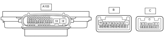
Disconnect the A103 No. 1 headlight ECU sub-assembly RH connector.
-
Measure the resistance and voltage according to the value(s) in the table below.
Terminal No. (Symbol) Wiring Color Terminal Description Condition Specified Condition A103-4 (IG) - Body ground GR - Body ground Ignition power supply Ignition switch off Below 1 V Ignition switch ON 11 to 14 V A103-13 (ECUB) - Body ground G-B - Body ground Power supply Ignition switch off Below 1 V Ignition switch ON 11 to 14 V A103-12 (GND) - Body ground W-B - Body ground Ground Always Below 1 Ω -
Reconnect the A103 No. 1 headlight ECU sub-assembly RH connector.
Tech Tips
-
Since the A103 No. 1 headlight ECU sub-assembly RH connector is a waterproof type connector, the voltage and pulses cannot be checked directly. The values listed are for reference only.
-
Since the B and C No. 1 headlight ECU sub-assembly RH connector is connected inside the headlight assembly, the voltage and pulses cannot be checked directly. The values listed are for reference only.
-
-
Measure the voltage and check of pulses according to the value(s) in the table below.
Terminal No. (Symbol) Wiring Color Terminal Description Condition Specified Condition A103-11 (TNS) - Body ground G - Body ground Right turn signal light signal input Ignition switch ON, right turn signal light off Below 1 V Ignition switch ON, right turn signal light blinking 11 to 14 V ←→ Below 1 V B-4 - B-3 - Low beam headlights drive output Low beam headlights off Below 1 V Low beam headlights on 13.47 to 19.62 V B-7 - B-17 - Headlight leveling motor power source Ignition switch off Below 1 V Ignition switch ON 11 to 14 V B-9 - B-13 - Left turn signal light signal output Ignition switch ON, left turn signal light off Below 1 V Ignition switch ON, left turn signal light blinking 11 to 14 V ←→ Below 1 V B-16 - B-11 - Clearance lights/daytime running lights control signal output Clearance light and daytime running light off Below 1 V Clearance light and daytime running light on Pulse generation B-20 - B-11 - Clearance lights/daytime running lights power source Clearance light and daytime running light off Below 1 V Clearance light and daytime running light on 11 to 14 V C-8 - C-7 - High beam headlights drive output High beam headlights off Below 1 V High beam headlights on 8.11 to 11.75 V
-
-
CHECK COMBINATION METER ASSEMBLY