LIGHTING SYSTEM(for Halogen Headlight) Taillight Relay Circuit
DESCRIPTION
The main body ECU (multiplex network body ECU) receives headlight dimmer switch information signals and illuminates the clearance lights, taillights and license plate light.
WIRING DIAGRAM
Figure 1. except 5L-E:
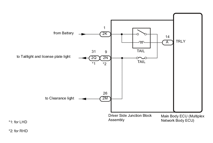
Figure 2. for 5L-E:

CAUTION / NOTICE / HINT
Note
-
Inspect the bulbs and fuses for circuits related to this system before performing the following procedure.
-
w/ Entry and Start System:
Before replacing the main body ECU (multiplex network body ECU), refer to Service Bulletin.
PROCEDURE
-
PERFORM ACTIVE TEST USING GTS
-
Using the GTS, perform the Active Test.
Main Body Tester Display Test Part Control Range Diagnostic Note Taillight Relay Clearance lights, taillights and license plate light OFF or ON - OK Clearance lights, taillights and license plate light turn on. Result Proceed to OK NG
OK 
PROCEED TO NEXT SUSPECTED AREA SHOWN IN PROBLEM SYMPTOMS TABLE Click here
NG 
-
-
CHECK DRIVER SIDE JUNCTION BLOCK ASSEMBLY
-
Remove the driver side junction block assembly.
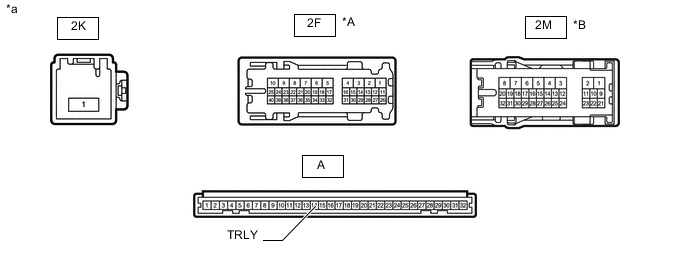
*A except 5L-E *B for 5L-E *a Component without harness connected
(Driver Side Junction Block Assembly)
- - -
Remove the main body ECU (multiplex network body ECU) from the driver side junction block assembly.
-
Measure the voltage according to the value(s) in the table below.
Standard Voltage except 5L-E Tester Connection Condition Specified Condition 2M-26 - Battery negative (-) terminal Battery not connected to 2K-1 and A-14 (TRLY) Below 1 V Battery positive (+) → 2K-1
Battery negative (-) → A-14 (TRLY)
11 to 14 V for 5L-E Tester Connection Condition Specified Condition 2F-7 - Battery negative (-) terminal Battery not connected to 2K-1 and A-14 (TRLY) Below 1 V Battery positive (+) → 2K-1
Battery negative (-) → A-14 (TRLY)
11 to 14 V Result Proceed to OK NG
OK
REPLACE MAIN BODY ECU (MULTIPLEX NETWORK BODY ECU) Click here
NG
REPLACE DRIVER SIDE JUNCTION BLOCK ASSEMBLY Click here
-