LIGHTING SYSTEM(for Halogen Headlight) Front Fog Light Circuit
DESCRIPTION
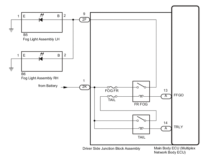
The main body ECU (multiplex network body ECU) controls the front fog light.
WIRING DIAGRAM
Figure 1. except 5L-E:
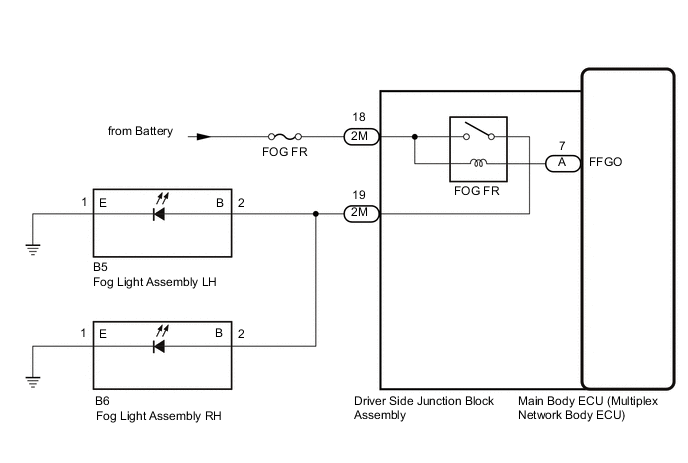
Figure 2. for 5L-E:
CAUTION / NOTICE / HINT
Note
-
Inspect the fuse for circuits related to this system before performing the follow procedure.
-
w/ Entry and Start System:
Before replacing the main body ECU (multiplex network body ECU), refer to Service Bulletin.
PROCEDURE
-
PERFORM ACTIVE TEST USING GTS
-
Using the GTS, perform the Active Test.
Main Body Tester Display Measurement Item Control Range Diagnostic Note Front Fog Light Relay Front fog lights OFF or ON Light control switch in Tail or Head position. OK Front fog lights turn on. Result Result Proceed to OK A NG (except 5L-E) B NG (for 5L-E) C
A 
PROCEED TO NEXT SUSPECTED AREA SHOWN IN PROBLEM SYMPTOMS TABLE Click here
C 
CHECK HARNESS AND CONNECTOR (DRIVER SIDE JUNCTION BLOCK ASSEMBLY - FOG LIGHT ASSEMBLY AND BATTERY) Click here
B 
-
-
CHECK HARNESS AND CONNECTOR (DRIVER SIDE JUNCTION BLOCK ASSEMBLY - FOG LIGHT ASSEMBLY AND BATTERY)
-
Disconnect the 2M driver side junction block assembly connector.
-
Disconnect the B5 fog light assembly LH connector.
-
Disconnect the B6 fog light assembly RH connector.
-
Measure the voltage according to the value(s) in the table below.
Standard Voltage Tester Connection Condition Specified Condition 2M-18 - Body ground Always 11 to 14 V -
Measure the resistance according to the value(s) in the table below.
Standard Resistance Tester Connection Condition Specified Condition 2M-19 - B5-2 (B) Always Below 1 Ω 2M-19 or B5-2 (B) - Body ground Always 10 kΩ or higher Result Proceed to OK NG
NG
REPAIR OR REPLACE HARNESS OR CONNECTOR
OK
-
-
CHECK DRIVER SIDE JUNCTION BLOCK ASSEMBLY
-
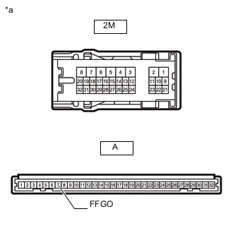
*a Component without harness connected
(Driver Side Junction Block Assembly)
Remove the driver side junction block assembly.
-
Remove the main body ECU (multiplex network body ECU) from the driver side junction block assembly.
-
Measure the voltage according to the value(s) in the table below.
Standard Voltage Tester Connection Condition Specified Condition 2M-19 - Battery negative (-) terminal Battery not connected to 2M-18 and A-7 (FFGO) Below 1 V Battery positive (+) → 2M-18
Battery negative (-) → A-7 (FFGO)
11 to 14 V Result Proceed to OK NG
OK
REPLACE MAIN BODY ECU (MULTIPLEX NETWORK BODY ECU) Click here
NG
REPLACE DRIVER SIDE JUNCTION BLOCK ASSEMBLY Click here
-
-
CHECK HARNESS AND CONNECTOR (DRIVER SIDE JUNCTION BLOCK ASSEMBLY - FOG LIGHT ASSEMBLY AND BATTERY)
-
Disconnect the 2K and 2F driver side junction block assembly connectors.
-
Disconnect the B5 fog light assembly LH connector.
-
Disconnect the B6 fog light assembly RH connector.
-
Measure the voltage according to the value(s) in the table below.
Standard Voltage Tester Connection Condition Specified Condition 2K-1 - Body ground Always 11 to 14 V -
Measure the resistance according to the value(s) in the table below.
Standard Resistance Tester Connection Condition Specified Condition 2F-9 - B5-2 (B) Always Below 1 Ω 2F-9 or B5-2 (B) - Body ground Always 10 kΩ or higher Result Proceed to OK NG
NG
REPAIR OR REPLACE HARNESS OR CONNECTOR
OK
-
-
CHECK DRIVER SIDE JUNCTION BLOCK ASSEMBLY
-
Remove the driver side junction block assembly.
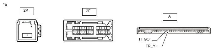
*a Component without harness connected
(Driver Side Junction Block Assembly)
- - -
Remove the main body ECU (multiplex network body ECU) from the driver side junction block assembly.
-
Measure the voltage according to the value(s) in the table below.
Standard Voltage Tester Connection Condition Specified Condition 2F-9 - Battery negative (-) terminal Battery not connected to 2K-1, A-13 (FFGO) and A-14 (TRLY) Below 1 V Battery positive (+) → 2K-1
Battery negative (-) → A-13 (FFGO) and A-14 (TRLY)
11 to 14 V Result Proceed to OK NG
OK
REPLACE MAIN BODY ECU (MULTIPLEX NETWORK BODY ECU) Click here
NG
REPLACE DRIVER SIDE JUNCTION BLOCK ASSEMBLY Click here
-