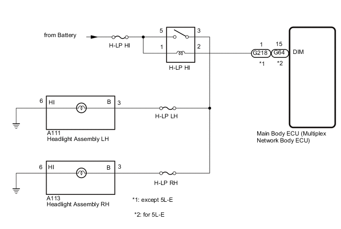
LIGHTING SYSTEM(for Halogen Headlight) Headlight (HI-BEAM) Circuit
DESCRIPTION
The main body ECU (multiplex network body ECU) receives headlight dimmer switch information signals and illuminates the high beam headlights.
WIRING DIAGRAM
CAUTION / NOTICE / HINT
Note
-
Inspect the fuses for circuits related to this system before performing the following procedure.
-
w/ Entry and Start System:
Before replacing the main body ECU (multiplex network body ECU), refer to Service Bulletin.
PROCEDURE
-
PERFORM ACTIVE TEST USING GTS
-
Using the GTS, perform the Active Test.
Main Body Tester Display Test Part Control Range Diagnostic Note Head Light Hi High beam headlights OFF or ON - OK High beam headlights turn on. Result Proceed to OK NG
OK 
PROCEED TO NEXT SUSPECTED AREA SHOWN IN PROBLEM SYMPTOMS TABLE Click here
NG 
-
-
INSPECT HEADLIGHT RELAY (H-LP HI)
-
Remove the headlight relay (H-LP HI) from the engine room relay block and junction block.
-
Inspect the headlight relay (H-LP HI).
Result Proceed to OK NG
NG
REPLACE HEADLIGHT RELAY (H-LP HI)
OK
-
-
CHECK HARNESS AND CONNECTOR (HEADLIGHT RELAY [H-LP HI] - BATTERY)
-
Remove the headlight relay (H-LP HI) from the engine room relay block and junction block.
-
Measure the voltage according to the value(s) in the table below.
Standard Voltage Tester Connection Condition Specified Condition Headlight relay (H-LP HI) terminal 1 - Body ground Always 11 to 14 V Headlight relay (H-LP HI) terminal 5 - Body ground Always 11 to 14 V Result Proceed to OK NG
NG
REPAIR OR REPLACE HARNESS OR CONNECTOR
OK
-
-
CHECK HARNESS AND CONNECTOR (HEADLIGHT DIMMER RELAY [DIMMER] - MAIN BODY ECU [MULTIPLEX NETWORK BODY ECU] AND HEADLIGHT ASSEMBLY)
-
Remove the headlight dimmer relay (DIMMER) from the engine room relay block and junction block.
-
Disconnect the G218*1 or G64*2 main body ECU (multiplex network body ECU) connector.
-
*1: except 5L-E
-
*2: for 5L-E
-
-
Disconnect the A111 headlight assembly LH connector.
-
Disconnect the A113 headlight assembly RH connector.
-
Measure the resistance according to the value(s) in the table below.
Standard Resistance except 5L-E Tester Connection Condition Specified Condition Headlight relay (H-LP HI) terminal 2 - G218-1 (DIM) Always Below 1 Ω Headlight relay (H-LP HI) terminal 3 - A111-3 (B) Always Below 1 Ω Headlight relay (H-LP HI) terminal 2 or G218-1 (DIM) - Body ground Always 10 kΩ or higher Headlight relay (H-LP HI) terminal 3 or A111-3 (B) - Body ground Always 10 kΩ or higher for 5L-E Tester Connection Condition Specified Condition Headlight relay (H-LP HI) terminal 2 - G64-15 (DIM) Always Below 1 Ω Headlight relay (H-LP HI) terminal 3 - A111-3 (B) Always Below 1 Ω Headlight relay (H-LP HI) terminal 2 or G64-15 (DIM) - Body ground Always 10 kΩ or higher Headlight relay (H-LP HI) terminal 3 or A111-3 (B) - Body ground Always 10 kΩ or higher Result Proceed to OK NG
OK
REPLACE MAIN BODY ECU (MULTIPLEX NETWORK BODY ECU) Click here
NG
REPAIR OR REPLACE HARNESS OR CONNECTOR
-