LIGHTING SYSTEM(for Halogen Headlight) Daytime Running Light Relay Circuit
DESCRIPTION
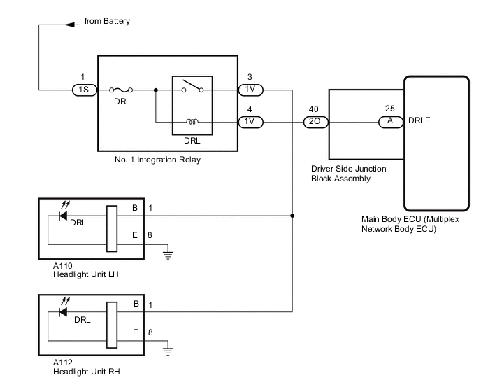
The main body ECU (multiplex network body ECU) controls the daytime running lights.
WIRING DIAGRAM
CAUTION / NOTICE / HINT
Note
-
Inspect the fuses for circuits related to this system before performing the following procedure.
-
w/ Entry and Start System:
Before replacing the main body ECU (multiplex network body ECU), refer to Registration.
PROCEDURE
-
PERFORM ACTIVE TEST USING GTS
-
Using the GTS, perform the Active Test.
Main Body Tester Display Test Part Control Range Diagnostic Note Daytime Running Light Daytime running lights OFF or ON - OK Daytime running lights turn on. Result Proceed to OK NG
OK 
PROCEED TO NEXT SUSPECTED AREA SHOWN IN PROBLEM SYMPTOMS TABLE Click here
NG 
-
-
INSPECT NO. 1 INTEGRATION RELAY (DRL)
-
Remove the No. 1 integration relay (DRL).
-
Inspect the No. 1 integration relay (DRL).
Result Proceed to OK NG
NG
REPLACE NO. 1 INTEGRATION RELAY (DRL) Click here
OK
-
-
CHECK HARNESS AND CONNECTOR (NO. 1 INTEGRATION RELAY - BATTERY)
-
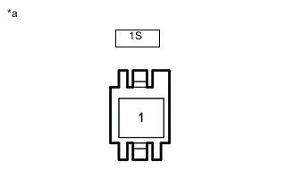
*a Front view of wire harness connector
(to No. 1 Integration Relay)
Remove the No. 1 integration relay.
-
Measure the voltage according to the value(s) in the table below.
Standard Voltage Tester Connection Condition Specified Condition 1S-1 - Body ground Always 11 to 14 V Result Proceed to OK NG
NG
REPAIR OR REPLACE HARNESS OR CONNECTOR
OK
-
-
CHECK HARNESS AND CONNECTOR (NO. 1 INTEGRATION RELAY - DRIVER SIDE JUNCTION BLOCK ASSEMBLY AND HEADLIGHT UNIT)
-
Remove the No. 1 integration relay.
-
Disconnect the 2O driver side junction block assembly connector.
-
Disconnect the A110 headlight unit LH connector.
-
Disconnect the A112 headlight unit RH connector.
-
Measure the resistance according to the value(s) in the table below.
Standard Resistance Tester Connection Condition Specified Condition 1V-4 - 2O-40 Always Below 1 Ω 1V-3 - A110-1 Always Below 1 Ω 1V-4 or 2O-40 - Body ground Always 10 kΩ or higher 1V-3 or A110-1 - Body ground Always 10 kΩ or higher Result Proceed to OK NG
NG
REPAIR OR REPLACE HARNESS OR CONNECTOR
OK
-
-
CHECK DRIVER SIDE JUNCTION BLOCK ASSEMBLY
-
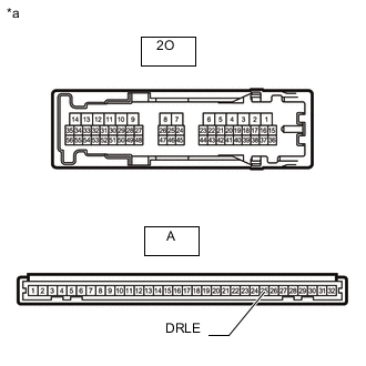
*a Component without harness connected
(Driver Side Junction Block Assembly)
Remove the driver side junction block assembly.
-
Remove the main body ECU (multiplex network body ECU) from the driver side junction block assembly.
-
Measure the resistance according to the value(s) in the table below.
Standard Resistance Tester Connection Condition Specified Condition 2O-40 - A-25 (DRLE) Always Below 1 Ω Result Proceed to OK NG
OK
REPLACE MAIN BODY ECU (MULTIPLEX NETWORK BODY ECU) Click here
NG
REPLACE DRIVER SIDE JUNCTION BLOCK ASSEMBLY Click here
-