LIGHTING SYSTEM Hazard Warning Switch Circuit
DESCRIPTION
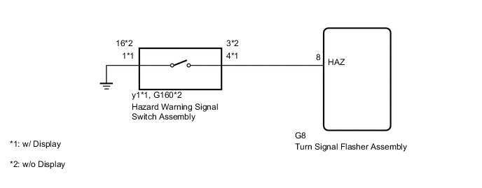
The turn signal flasher receives a hazard warning signal switch information signal and illuminates the turn signal lights.
WIRING DIAGRAM
PROCEDURE
-
INSPECT HAZARD WARNING SIGNAL SWITCH ASSEMBLY
-
w/ Display
-
Remove the hazard warning signal switch Click here.
-
Measure the resistance according to the value(s) in the table below.
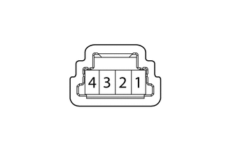
Standard Resistance Tester Connection Switch Condition Specified Condition 1 - 4 Hazard warning signal switch on Below 1 Ω Hazard warning signal switch off 10 kΩ or higher
-
-
w/o Display
-
Remove the hazard warning signal switch Click here.
-
Measure the resistance according to the value(s) in the table below.
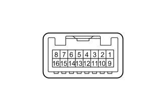
Standard Resistance Tester Connection Switch Condition Specified Condition 16 - 3 Hazard warning signal switch on Below 1 Ω Hazard warning signal switch off 10 kΩ or higher
-
NG 
REPLACE HAZARD WARNING SIGNAL SWITCH ASSEMBLY Click here
OK 
-
-
CHECK HARNESS AND CONNECTOR (HAZARD WARNING SIGNAL SWITCH ASSEMBLY - TURN SIGNAL FLASHER ASSEMBLY AND BODY GROUND)
-
*1: w/ Navigation System
-
*2: w/o Navigation System
-
Disconnect the y1*1 or G160*2 hazard warning signal switch connector.
-
Disconnect the G8 turn signal flasher connector.
-
Measure the resistance according to the value(s) in the table below.
Standard Resistance w/ Navigation System Tester Connection Condition Specified Condition y1- 4 - 8 (HAZ) Always Below 1 Ω y1-1 - Body ground Always Below 1 Ω y1-4 - Body ground Always 10 kΩ or higher w/o Navigation System Tester Connection Condition Specified Condition G160-3 - 8 (HAZ) Always Below 1 Ω G160-16 - Body ground Always Below 1 Ω G160-3 - Body ground Always 10 kΩ or higher
OK
PROCEED TO NEXT SUSPECTED AREA SHOWN IN PROBLEM SYMPTOMS TABLE Click here
NG
REPAIR OR REPLACE HARNESS OR CONNECTOR
-