LIGHTING SYSTEM(for LED Headlight) Taillight Relay Circuit
DESCRIPTION
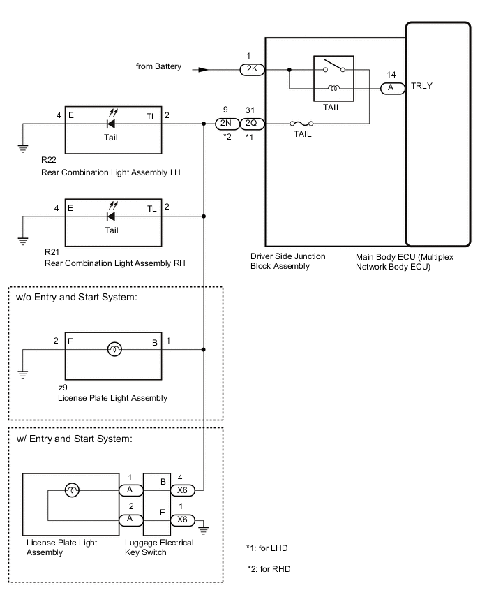
The main body ECU (multiplex network body ECU) controls the taillight and license plate light.
WIRING DIAGRAM
CAUTION / NOTICE / HINT
Note
-
Inspect the fuse for circuits related to this system before performing the follow procedure.
-
Before replacing the main body ECU (multiplex network body ECU), refer to Service Bulletin.
PROCEDURE
-
PERFORM ACTIVE TEST USING GTS
-
Using the GTS, perform the Active Test.
Main Body Tester Display Measurement Item Control Range Diagnostic Note Taillight Relay Taillights and license plate light OFF or ON - OK Tail relay operates (taillights and license plate light turn on). Result Proceed to OK NG
OK 
PROCEED TO NEXT SUSPECTED AREA SHOWN IN PROBLEM SYMPTOMS TABLE Click here
NG 
-
-
CHECK HARNESS AND CONNECTOR (TAILLIGHT CIRCUIT)
-
*1: for LHD
-
*2: for RHD
-
*3: w/o Entry and Start System
-
*4: w/ Entry and Start System
-
Disconnect the 2Q*1, 2N*2 and 2K driver side junction block assembly connectors.
-
Disconnect the R22 rear combination light assembly LH connector.
-
Disconnect the R21 rear combination light assembly RH connector.
-
Disconnect the z9 license plate light assembly connector.*3
-
Disconnect the X6 luggage electrical key switch connector.*4
-
Measure the voltage according to the value(s) in the table below.
Standard Voltage Tester Connection Condition Specified Condition 2K-1 - Body ground Always 11 to 14 V -
Measure the resistance according to the value(s) in the table below.
Standard Resistance for LHD Tester Connection Condition Specified Condition 2Q-31 - R22-2 (TL) Always Below 1 Ω 2Q-31 - Body ground Always 10 kΩ or higher for RHD Tester Connection Condition Specified Condition 2N-9 - R22-2 (TL) Always Below 1 Ω 2N-9 - Body ground Always 10 kΩ or higher Result Proceed to OK NG
NG
REPAIR OR REPLACE HARNESS OR CONNECTOR
OK
-
-
CHECK DRIVER SIDE JUNCTION BLOCK ASSEMBLY
-
Remove the driver side junction block assembly.
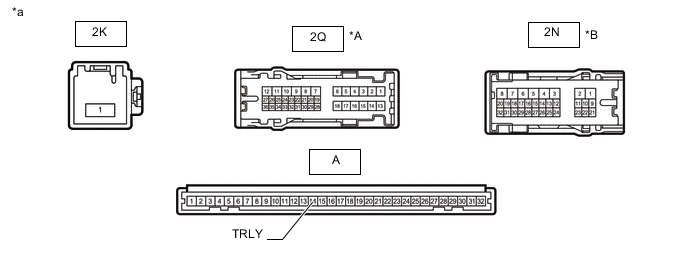
*A for LHD *B for RHD *a Component without harness connected
(Driver Side Junction Block Assembly)
- - -
Remove the main body ECU (multiplex network body ECU) from the driver side junction block assembly.
-
Measure the voltage according to the value(s) in the table below.
Standard Voltage for LHD Tester Connection Condition Specified Condition 2Q-31 - Battery negative (-) terminal Battery not connected to 2K-1 and A-14 (TRLY) Below 1 V Battery positive (+) → 2K-1
Battery negative (-) → A-14 (TRLY)
11 to 14 V for RHD Tester Connection Condition Specified Condition 2N-9 - Battery negative (-) terminal Battery not connected to 2K-1 and A-14 (TRLY) Below 1 V Battery positive (+) → 2K-1
Battery negative (-) → A-14 (TRLY)
11 to 14 V Result Proceed to OK NG
OK
REPLACE MAIN BODY ECU (MULTIPLEX NETWORK BODY ECU) Click here
NG
REPLACE DRIVER SIDE JUNCTION BLOCK ASSEMBLY Click here
-