LIGHTING SYSTEM(for LED Headlight) Front Fog Light Circuit
DESCRIPTION
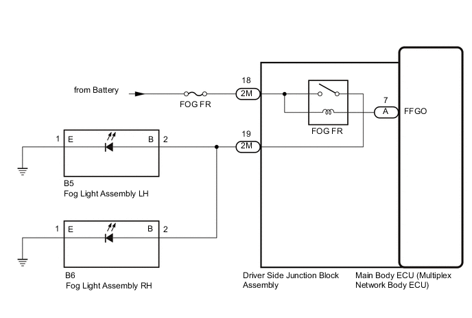
The main body ECU (multiplex network body ECU) controls the front fog light.
WIRING DIAGRAM
CAUTION / NOTICE / HINT
Note
-
Inspect the fuse for circuits related to this system before performing the follow procedure.
-
Before replacing the main body ECU (multiplex network body ECU), refer to Service Bulletin.
PROCEDURE
-
PERFORM ACTIVE TEST USING GTS
-
Using the GTS, perform the Active Test.
Main Body Tester Display Measurement Item Control Range Diagnostic Note Front Fog Light Relay Front fog lights OFF or ON - OK Front fog light relay operates (front fog lights turn on). Result Proceed to OK NG
OK 
PROCEED TO NEXT SUSPECTED AREA SHOWN IN PROBLEM SYMPTOMS TABLE Click here
NG 
-
-
CHECK HARNESS AND CONNECTOR (DRIVER SIDE JUNCTION BLOCK ASSEMBLY - FOG LIGHT ASSEMBLY AND BATTERY)
-
Disconnect the 2M driver side junction block assembly connector.
-
Disconnect the B5 fog light assembly LH connector.
-
Disconnect the B6 fog light assembly RH connector.
-
Measure the voltage according to the value(s) in the table below.
Standard Voltage Tester Connection Condition Specified Condition 2M-18 - Body ground Always 11 to 14 V -
Measure the resistance according to the value(s) in the table below.
Standard Resistance Tester Connection Condition Specified Condition 2M-19 - B5-2 (B) Always Below 1 Ω 2M-19 - Body ground Always 10 kΩ or higher Result Proceed to OK NG
NG
REPAIR OR REPLACE HARNESS OR CONNECTOR
OK
-
-
CHECK DRIVER SIDE JUNCTION BLOCK ASSEMBLY
-
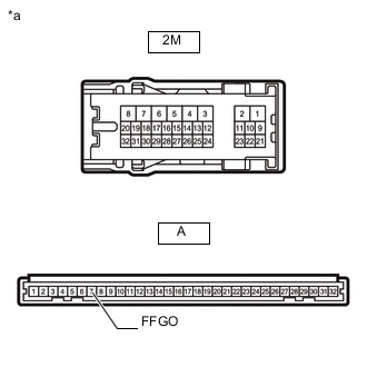
*a Component without harness connected
(Driver Side Junction Block Assembly)
Remove the driver side junction block assembly.
-
Remove the main body ECU (multiplex network body ECU) from the driver side junction block assembly.
-
Measure the voltage according to the value(s) in the table below.
Standard Voltage Tester Connection Condition Specified Condition 2M-19 - Battery negative (-) terminal Battery not connected to 2M-18 and A-7 (FFGO) Below 1 V Battery positive (+) → 2M-18
Battery negative (-) → A-7 (FFGO)
11 to 14 V Result Proceed to OK NG
OK
REPLACE MAIN BODY ECU (MULTIPLEX NETWORK BODY ECU) Click here
NG
REPLACE DRIVER SIDE JUNCTION BLOCK ASSEMBLY Click here
-