FRONT WIPER MOTOR INSTALLATION

CAUTION / NOTICE / HINT
Tech Tips
-
Use the same procedure as for the LHD and RHD vehicles.
-
The procedure listed below is for the LHD vehicles.
PROCEDURE
-
INSTALL WIPER MOTOR WIRE
-
Attach the claw to install the wiper motor wire.
-
-
INSTALL WINDSHIELD WIPER MOTOR ASSEMBLY
-
Using a T30 "TORX" socket wrench, install the wiper motor assembly with the 2 bolts.
- Torque:
- 7.5 N*m { 76 kgf*cm, 66 in.*lbf }
-
Connect the connector.
-
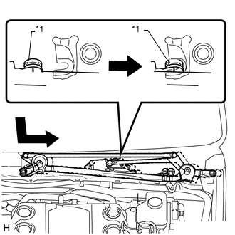
w/o Spring:
-
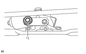
*1 Crank Arm Pivot 
MP grease Apply MP grease to the crank arm pivot of the front wiper crank.
-
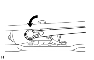
Connect the windshield wiper link rod to the crank arm pivot of the front wiper crank.
-
-
-
INSTALL FRONT WIPER CRANK SUB-ASSEMBLY (for RHD, w/ Spring)
-
Check the automatic stop position.
-
Check that the motor stops automatically at the automatic stop position.
-
-
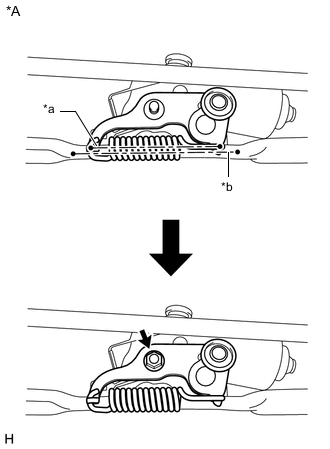
*A Front Wiper Crank Set Position *a Center Line of Crank Arm Spring *b Center Line of Wiper Link Stay Install the front wiper crank sub-assembly to the windshield wiper motor assembly with the nut so that center lines of the crank arm spring and wiper link stay are parallel.
- Torque:
- 8.5 N*m { 87 kgf*cm, 6 ft.*lbf }
Tech Tips
Hold the front wiper crank sub-assembly by hand when tightening the nut.
-
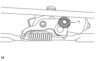
*1 Crank Arm Pivot MP grease Apply MP grease to the crank arm pivot of the front wiper crank sub-assembly.
-
Connect the windshiele wiper link rod of the windshield wiper link to the front wiper crank sub-assembly.
-
-
INSTALL WINDSHIELD WIPER MOTOR AND LINK
-
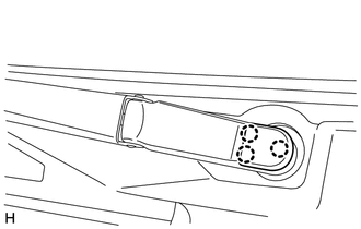
*1 Grommet Attach the grommet as shown in the illustration.
Note
Be careful not to damage the windshield when installing the windshield wiper motor and link.
-
Install the windshield wiper motor and link with the 2 bolts.
- Torque:
- 7.0 N*m { 71 kgf*cm, 62 in.*lbf }
-
Connect the connector.
-
Attach the clamp.
-
-
INSTALL COWL TOP VENTILATOR LOUVER SUB-ASSEMBLY
-
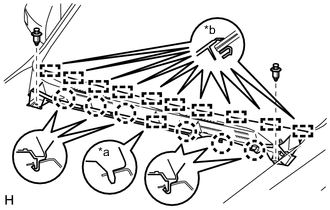
*a Guide (A) *b Guide (B) Attach the 10 guides (B).
-
Attach the 6 claws and guide (A) as shown in the illustration.
-
Install the cowl top ventilator louver sub-assembly with the 2 clips.
-
-
INSTALL CENTER NO. 2 COWL TOP VENTILATOR LOUVER
-
Attach the 2 claws and 3 guides to install the center No. 2 cowl top ventilator louver.
-
-
INSTALL HOOD TO COWL TOP SEAL
-
Attach the 2 clips and 7 claws to install the hood to cowl top seal.
-
-
INSTALL FRONT WIPER ARM AND BLADE ASSEMBLY RH
-
Operate the wiper and stop the windshield wiper motor assembly at the automatic stop position.
-

*a Wiper Arm Serration *b Wire Brush *c Wiper Pivot Serration When reusing the front wiper arm and blade assembly RH:
-
Clean the wiper arm serrations.
-
Clean the wiper pivot serrations.
Note
Do not grind the wiper arm serrations excessively.
-
-
Turn the ignition switch to ON (IG).
-
Operate the wiper switch and stop the windshield wiper motor assembly at the automatic stop (park) position.
-
Turn the ignition switch off.
-
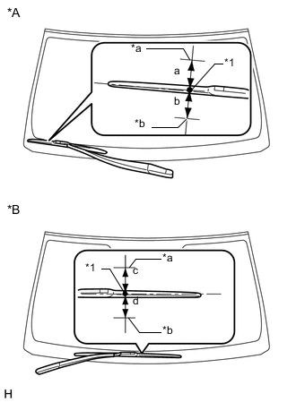
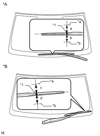
*A for LHD *B for RHD *1 Ceramic Dot *a Upper Limit *b Lower Limit Install the front wiper arm and blade assembly RH with the nut to the position shown in the illustration.
- Torque:
- 25 N*m { 255 kgf*cm, 18 ft.*lbf }
Standard Area Standard Condition a 7.5 mm (0.295 in.) b 7.5 mm (0.295 in.) c 7.5 mm (0.295 in.) d 7.5 mm (0.295 in.) Tech Tips
-
Hold the wiper arm by hand while tightening the nut.
-
Raise and lower the wiper arm a few times to confirm that it has settled to the specified position.
-
-
INSTALL FRONT WIPER ARM AND BLADE ASSEMBLY LH
-
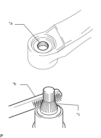
*a Wiper Arm Serration *b Wire Brush *c Wiper Pivot Serration When reusing the front wiper arm and blade assembly LH:
-
Clean the wiper arm serrations.
-
Clean the wiper pivot serrations.
Note
Do not grind the wiper arm serrations excessively.
-
-
Turn the ignition switch to ON (IG).
-
Operate the wiper switch and stop the windshield wiper motor assembly at the automatic stop (park) position.
-
Turn the ignition switch off.
-
*A for LHD *B for RHD *1 Ceramic Dot *a Upper Limit *b Lower Limit Install the front wiper arm and blade assembly LH with the nut to the position shown in the illustration.
- Torque:
- 25 N*m { 255 kgf*cm, 18 ft.*lbf }
Standard Area Standard Condition a 7.5 mm (0.295 in.) b 7.5 mm (0.295 in.) c 7.5 mm (0.295 in.) d 7.5 mm (0.295 in.) Tech Tips
-
Hold the wiper arm by hand while tightening the nut.
-
Raise and lower the wiper arm a few times to confirm that it has settled to the specified position.
-
Operate the front wipers while spraying washer fluid on the windshield glass. Make sure that the front wipers function properly and there is no interference with the vehicle body.
-
-
INSTALL WINDSHIELD WIPER ARM COVER
-
Attach the 3 claws to install the windshield wiper arm cover.
Tech Tips
Use the same procedure for the RH side and LH side.
-
-
INSTALL FRONT FENDER TO COWL SIDE SEAL LH
-
Attach the 3 claws and guide to install the front fender to cowl side seal LH.
-
-
INSTALL FRONT FENDER TO COWL SIDE SEAL RH
Tech Tips
Use the same procedure for the LH side.
-
INSTALL FRONT FENDER SIDE PANEL PROTECTOR LH
-
Attach the 3 clips and guide to install the front fender side panel protector LH.
-
-
INSTALL FRONT FENDER SIDE PANEL PROTECTOR RH
Tech Tips
Use the same procedure for the LH side.
-
INSTALL UPPER RADIATOR SUPPORT SEAL
-
CONNECT CABLE TO NEGATIVE BATTERY TERMINAL
Note
When disconnecting the cable, some systems need to be initialized after the cable is reconnected.