WIPER AND WASHER SYSTEM Washer Nozzle Heater Circuit
DESCRIPTION
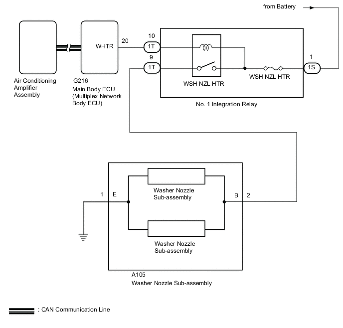
The main body ECU (multiplex network body ECU) receives ambient air temperature information from the air conditioning amplifier assembly via CAN communication.
The washer nozzle heater assembly controls the main body ECU (multiplex network body ECU) and operates the washer nozzle heater assembly according to the ambient temperature.
WIRING DIAGRAM
CAUTION / NOTICE / HINT
Note
Inspect the fuses for circuits related to this system before performing the following inspection procedure.
PROCEDURE
-
PERFORM ACTIVE TEST USING GTS
-
Using the GTS, perform the Active Test.
Main Body Tester Display Test Part Control Range Diagnostic Note Washer Nozzle Heater Washer nozzle heater operation ON/OFF - -
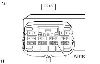
*a Componet with harness connected
Main Body ECU (Multiplex Network Body ECU)
Measure the voltage according to the value(s) in the table below.
Standard Voltage Tester Connection Switch Condition Specified Condition G216-20 (WHTR) - Body ground Ignition switch ON, Active Test is not performed 11 to 14 V Ignition switch ON, Active Test is performed Below 1 V Result Proceed to OK NG
NG 
CHECK HARNESS AND CONNECTOR (NO. 1 INTEGRATION RELAY - BATTERY) Click here
OK 
-
-
INSPECT WASHER NOZZLE SUB-ASSEMBLY
-
Remove the washer nozzle sub-assembly.
-
Inspect the washer nozzle sub-assembly.
Result Proceed to OK NG
NG 
REPLACE WASHER NOZZLE SUB-ASSEMBLY Click here
OK
-
-
INSPECT NO. 1 INTEGRATION RELAY
-
Remove the No. 1 integration relay.
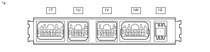
*a Component without harness connected
(No. 1 Integration Relay)
- - -
Measure the voltage according to the value(s) in the table below.
Standard Resistance Tester Connection Condition Specified Condition 1T-9 - Battery negative (-) Battery not connected to 1S-1 and 1T-10 Below 1 V Battery positive (+) → 1S-1
Battery negative (-) → 1T-10
11 to 14 V Result Proceed to OK NG
OK
REPAIR OR REPLACE HARNESS OR CONNECTOR
NG
REPLACE NO. 1 INTEGRATION RELAY Click here
-
-
CHECK HARNESS AND CONNECTOR (NO. 1 INTEGRATION RELAY - BATTERY)
-
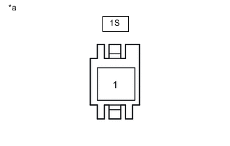
*a Front view of wire harness connector
(to No. 1 Integration Relay)
Disconnect the No. 1 integration relay connector.
-
Measure the voltage according to the value(s) in the table below.
Standard Voltage Tester Connection Condition Specified Condition 1S-1 - Body ground Always 11 to 14 V Result Proceed to OK NG
NG
REPAIR OR REPLACE HARNESS OR CONNECTOR
OK
-
-
CHECK HARNESS AND CONNECTOR (MAIN BODY ECU [MULTIPLEX NETWORK BODY ECU] - NO. 1 INTEGRATION RELAY)
-
Disconnect the G216 main body ECU (multiplex network body ECU) connector.
-
Disconnect the 1T No. 1 integration relay connector.
-
Measure the resistance according to the value(s) in the table below.
Standard Resistance Tester Connection Condition Specified Condition G216-20 (WHTR) - 1T-10 Always Below 1 Ω G216-20 (WHTR) - Body ground Always 10 kΩ or higher Result Proceed to OK NG
NG
REPAIR OR REPLACE HARNESS OR CONNECTOR
OK
-
-
INSPECT NO. 1 INTEGRATION RELAY
-
Remove the No. 1 integration relay.
*a Component without harness connected
(No. 1 Integration Relay)
- - -
Measure the voltage according to the value(s) in the table below.
Standard Resistance Tester Connection Condition Specified Condition 1T-9 - Battery negative (-) Battery not connected to 1S-1 and 1T-10 Below 1 V Battery positive (+) → 1S-1
Battery negative (-) → 1T-10
11 to 14 V Result Proceed to OK NG
OK
REPLACE MAIN BODY ECU (MULTIPLEX NETWORK BODY ECU) Click here
NG
REPLACE NO. 1 INTEGRATION RELAY Click here
-