WIPER AND WASHER SYSTEM Headlight Cleaner Switch Circuit
DESCRIPTION
This circuit detects the conditions (on or off) of the headlight cleaner switch assembly.
WIRING DIAGRAM
Figure 1. for Halogen Headlight:
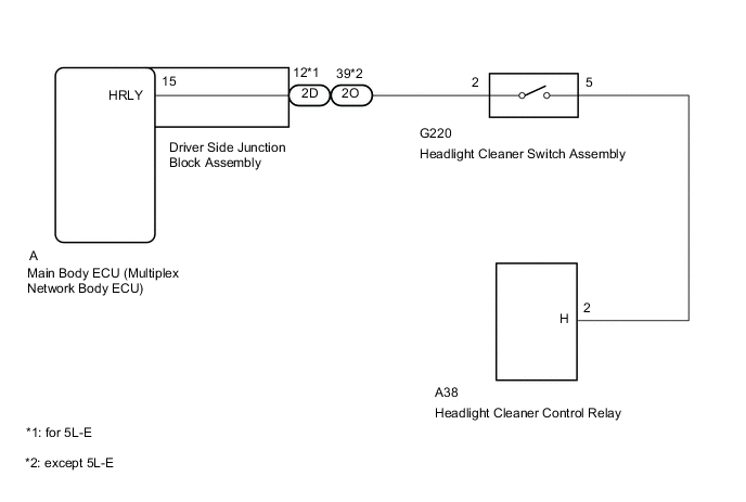
Figure 2. for LED Headlight:
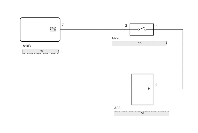
| *a | HLC |
| *b | Headlight Cleaner Switch Assembly |
| *c | No. 1 Headlight ECU Sub-assembly RH |
| *d | Headlight Cleaner Control Relay |
PROCEDURE
-
CHECK VEHICLE TYPE
-
Check vehicle type.
Result Result Proceed to for Halogen Headlight A for LED Headlight B
B 
INSPECT HEADLIGHT CLEANER SWITCH ASSEMBLY Click here
A 
-
-
INSPECT HEADLIGHT CLEANER SWITCH ASSEMBLY
-
Remove the headlight cleaner switch assembly.
-
Inspect the headlight cleaner switch assembly.
NG 
REPLACE HEADLIGHT CLEANER SWITCH ASSEMBLY Click here
OK
-
-
CHECK HARNESS AND CONNECTOR (HEADLIGHT CLEANER SWITCH ASSEMBLY - HEADLIGHT CLEANER CONTROL RELAY)
-
Disconnect the G220 headlight cleaner switch assembly connector.
-
Disconnect the A38 headlight cleaner control relay connector.
-
Measure the resistance according to the value(s) in the table below.
Standard Resistance Tester Connection Condition Specified Condition G220-5 - A38-2(H) Always Below 1 Ω G220-5 - Body ground Always 10 kΩ or higher
NG
REPAIR OR REPLACE HARNESS OR CONNECTOR
OK
-
-
CHECK HARNESS AND CONNECTOR (HEADLIGHT CLEANER SWITCH ASSEMBLY - MAIN BODY ECU [MULTIPLEX NETWORK BODY ECU])
-
Disconnect the G220 headlight cleaner switch assembly connector.
-
Remove the main body ECU (multiplex network body ECU) from the driver side junction block assembly.
-
Measure the resistance according to the value(s) in the table below.
Standard Resistance Tester Connection Condition Specified Condition G220-2 - A-15 (HRLY) Always Below 1 Ω G220-2 - Body ground Always 10 kΩ or higher
OK
PROCEED TO NEXT SUSPECTED AREA SHOWN IN PROBLEM SYMPTOMS TABLE Click here
NG
-
-
CHECK HARNESS AND CONNECTOR (DRIVER SIDE JUNCTION BLOCK ASSEMBLY - HEADLIGHT CLEANER SWITCH ASSEMBLY)
-
Disconnect the 2D*1 or 2O*2 driver side junction block assembly connector.
-
*1: for 5L-E
-
*2: except 5L-E
-
-
Disconnect the G220 headlight cleaner switch assembly connector.
-
Measure the resistance according to the value(s) in the table below.
Standard Resistance for 5L-E Tester Connection Condition Specified Condition 2D-12 - G220-2 Always Below 1 Ω 2D-12 - Body ground Always 10 kΩ or higher except 5L-E Tester Connection Condition Specified Condition 2O-39 - G220-2 Always Below 1 Ω 2O-39 - Body ground Always 10 kΩ or higher
OK
REPLACE DRIVER SIDE JUNCTION BLOCK ASSEMBLY Click here
NG
REPAIR OR REPLACE HARNESS OR CONNECTOR
-
-
INSPECT HEADLIGHT CLEANER SWITCH ASSEMBLY
-
Remove the headlight cleaner switch assembly.
-
Inspect the headlight cleaner switch assembly.
NG
REPLACE HEADLIGHT CLEANER SWITCH ASSEMBLY Click here
OK
-
-
CHECK HARNESS AND CONNECTOR (HEADLIGHT CLEANER SWITCH ASSEMBLY - HEADLIGHT CLEANER CONTROL RELAY)
-
Disconnect the G220 headlight cleaner switch assembly connector.
-
Disconnect the A38 headlight cleaner control relay connector.
-
Measure the resistance according to the value(s) in the table below.
Standard Resistance Tester Connection Condition Specified Condition G220-5 - A38-2(H) Always Below 1 Ω G220-5 - Body ground Always 10 kΩ or higher
NG
REPAIR OR REPLACE HARNESS OR CONNECTOR
OK
-
-
CHECK HARNESS AND CONNECTOR (HEADLIGHT CLEANER SWITCH ASSEMBLY - NO. 1 HEADLIGHT ECU SUB-ASSEMBLY RH)
-
Disconnect the G220 headlight cleaner switch assembly connector.
-
Disconnect the A103 No. 1 headlight ECU sub-assembly RH connector.
-
Measure the resistance according to the value(s) in the table below.
Standard Resistance Tester Connection Condition Specified Condition G220-2 - A103-7 (HLC) Always Below 1 Ω G220-2 - Body ground Always 10 kΩ or higher
OK
PROCEED TO NEXT SUSPECTED AREA SHOWN IN PROBLEM SYMPTOMS TABLE Click here
NG
REPAIR OR REPLACE HARNESS OR CONNECTOR
-