WIPER AND WASHER SYSTEM Rear Wiper does not Operate
DESCRIPTION
When the glass hatch is open, the rear wiper system cuts off the power supply to prevent the rear wiper and rear washer from operating.
WIRING DIAGRAM
Figure 1. for 5L-E:
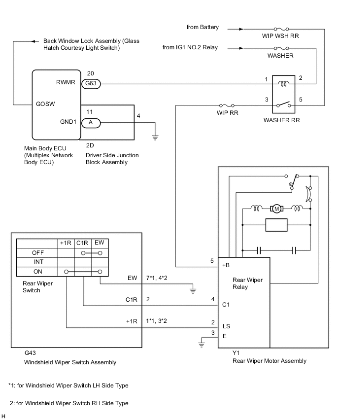
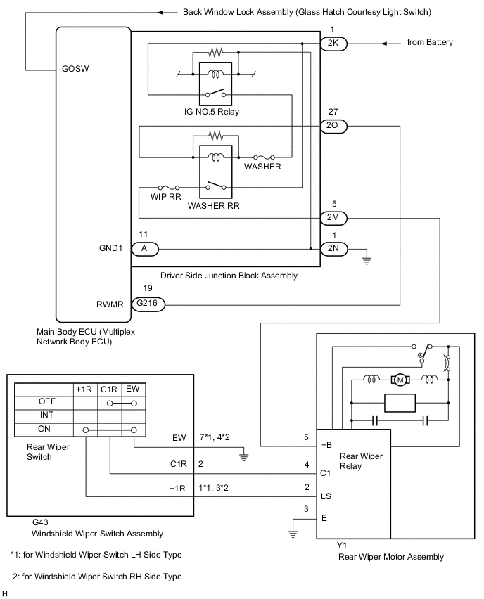
Figure 2. except 5L-E:
CAUTION / NOTICE / HINT
Note
Inspect the fuses for circuits related to this system before performing the following inspection procedure.
PROCEDURE
-
READ VALUE USING GTS (GLASS HATCH COURTESY SWITCH)
-
Use the Data List to check if the glass hatch opener is functioning properly Click here.
Main Body Tester Display Measurement Item/Range Normal Condition Diagnostic Note Glass Hatch Courtesy Switch Glass hatch courtesy switch signal / ON or OFF ON: Glass hatch open
OFF: Glass hatch closed
- OK On tester screen, each item changes between ON and OFF according to above chart. Result Result Proceed to OK A NG (for 5L-E) B NG (except 5L-E) C
B 
GO TO LIGHTING SYSTEM Click here
C
GO TO LIGHTING SYSTEM Click here
A 
-
-
PERFORM ACTIVE TEST USING GTS (REAR WIPER MOTOR)
-
Using the intelligent tester, perform the Active Test Click here.
Main Body Tester Display Test Part Control Range Diagnostic Note Rear Wiper Power Supply WASHER RR relay operation ON/OFF - OK Rear wiper motor operates. Result Result Proceed to OK A NG (for 5L-E) B NG (except 5L-E) C
A
REPLACE MAIN BODY ECU (MULTIPLEX NETWORK BODY ECU) Click here
C 
CHECK HARNESS AND CONNECTOR (DRIVER SIDE JUNCTION BLOCK ASSEMBLY - BATTERY AND BODY GROUND) Click here
B
-
-
INSPECT WASHER RR RELAY
-
Remove the WASHER RR relay from the engine room relay block, junction block.
-
Inspect the WASHER RR relay.
NG
REPLACE WASHER RR RELAY
OK
-
-
CHECK HARNESS AND CONNECTOR (WASHER RR RELAY - BATTERY)
-
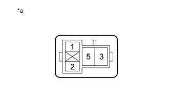
Text in Illustration *a Front view of wire harness connector
(to WASHER RR Relay)
Remove the WASHER RR relay from the engine room relay block, junction block.
-
Measure the voltage according to the value(s) in the table below.
Standard Voltage Tester Connection Condition Specified Condition WASHER RR relay terminal 2 - Body ground Ignition switch ON 11 to 14 V WASHER RR relay terminal 2 - Body ground Ignition switch off Below 1 V WASHER RR relay terminal 5 - Body ground Ignition switch ON 11 to 14 V WASHER RR relay terminal 5 - Body ground Ignition switch off Below 1 V
NG
REPAIR OR REPLACE HARNESS OR CONNECTOR
OK
-
-
CHECK HARNESS AND CONNECTOR (MAIN BODY ECU [MULTIPLEX NETWORK BODY ECU] - WASHER RR RELAY AND BODY GROUND)
-
Disconnect the G63 main body ECU (multiplex network body ECU) connector.
-
Remove the WASHER RR relay from the engine room relay block, junction block.
-
Measure the resistance according to the value(s) in the table below.
Standard Resistance Tester Connection Condition Specified Condition G63-20 (RWMR) - WASHER RR relay terminal 1 Always Below 1 Ω G63-20 (RWMR) - Body ground Always 10 kΩ or higher
NG
CHECK DRIVER SIDE JUNCTION BLOCK ASSEMBLY Click here
OK
-
-
CHECK HARNESS AND CONNECTOR (WASHER RR RELAY - REAR WIPER MOTOR ASSEMBLY)
-
Disconnect the Y1 rear wiper motor assembly connector.
-
Remove the WASHER RR relay from the engine room relay block, junction block.
-
Measure the resistance according to the value(s) in the table below.
Standard Resistance Tester Connection Condition Specified Condition Y1-5 (+B) - WASHER RR relay terminal 3 Always Below 1 Ω Y1-5 (+B) - Body ground Always 10 kΩ or higher
NG
REPAIR OR REPLACE HARNESS OR CONNECTOR
OK
-
-
INSPECT REAR WIPER MOTOR ASSEMBLY
-
Remove the rear wiper motor assembly.
-
Inspect the rear wiper motor assembly.
NG
REPLACE REAR WIPER MOTOR ASSEMBLY Click here
OK
-
-
CHECK HARNESS AND CONNECTOR (REAR WIPER MOTOR ASSEMBLY - BODY GROUND)
-
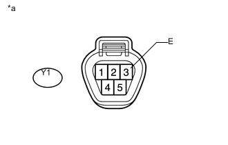
Text in Illustration *a Front view of wire harness connector
(to Rear Wiper Motor Assembly)
Disconnect the rear wiper motor assembly connector.
-
Measure the resistance according to the value(s) in the table below.
Standard Resistance Tester Connection Condition Specified Condition Y1-3 (E) - Body ground Always Below 1 Ω
NG
REPAIR OR REPLACE HARNESS OR CONNECTOR
OK
-
-
INSPECT WINDSHIELD WIPER SWITCH ASSEMBLY
-
Remove the windshield wiper switch assembly.
-
Inspect the windshield wiper switch assembly.
NG
REPLACE WINDSHIELD WIPER SWITCH ASSEMBLY Click here
OK
-
-
CHECK HARNESS AND CONNECTOR (WINDSHIELD WIPER SWITCH ASSEMBLY - REAR WIPER MOTOR ASSEMBLY AND BODY GROUND)
-
for Windshield Wiper Switch LH Side Type:
-
Disconnect the Y1 rear wiper motor assembly connector.
-
Disconnect the G43 windshield wiper switch assembly connector.
-
Measure the resistance according to the value(s) in the table below.
Standard Resistance Tester Connection Condition Specified Condition Y1-2 (LS) - G43-1 (+1R) Always Below 1 Ω Y1-4 (C1) - G43-2 (C1R) Always Below 1 Ω G43-7 (EW) - Body ground Always Below 1 Ω Y1-2 (LS) - Body ground Always 10 kΩ or higher Y1-4 (C1) - Body ground Always 10 kΩ or higher
-
-
for Windshield Wiper Switch RH Side Type:
-
Disconnect the Y1 rear wiper motor assembly connector.
-
Disconnect the G43 windshield wiper switch assembly connector.
-
Measure the resistance according to the value(s) in the table below.
Standard Resistance Tester Connection Condition Specified Condition Y1-2 (LS) - G43-3 (+1R) Always Below 1 Ω Y1-4 (C1) - G43-2 (C1R) Always Below 1 Ω G43-4 (EW) - Body ground Always Below 1 Ω Y1-2 (LS) - Body ground Always 10 kΩ or higher Y1-4 (C1) - Body ground Always 10 kΩ or higher
-
OK
REPLACE MAIN BODY ECU (MULTIPLEX NETWORK BODY ECU) Click here
NG
REPAIR OR REPLACE HARNESS OR CONNECTOR
-
-
CHECK HARNESS AND CONNECTOR (DRIVER SIDE JUNCTION BLOCK ASSEMBLY - BATTERY AND BODY GROUND)
-
Disconnect the driver side junction block assembly connectors.
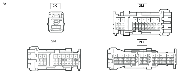
*a Front view of wire harness connector
(to Driver Side Junction Block Assembly)
- - -
Measure the voltage according to the value(s) in the table below.
Standard Voltage Tester Connection Condition Specified Condition 2K-1 - Body ground Always 11 to 14 V 2O-27 - Body ground Ignition switch ON 11 to 14 V Ignition switch off Below 1 V 2M-5 - Body ground Ignition switch ON 11 to 14 V Ignition switch off Below 1 V -
Measure the resistance according to the value(s) in the table below.
Standard Resistance Tester Connection Condition Specified Condition 2N-1 - Body ground Always Below 1 Ω
NG
REPAIR OR REPLACE HARNESS OR CONNECTOR
OK
-
-
CHECK HARNESS AND CONNECTOR (MAIN BODY ECU [MULTIPLEX NETWORK BODY ECU] - DRIVER SIDE JUNCTION BLOCK ASSEMBLY)
-
Disconnect the 2O driver side junction block assembly connector.
-
Disconnect the G216 main body ECU (multiplex network body ECU) connector.
-
Measure the resistance according to the value(s) in the table below.
Standard Resistance Tester Connection Condition Specified Condition G216-19 (RWMR) - 2O-27 Always Below 1 Ω A-11 (GND1) - Body ground Always Below 1 Ω G216-19 (RWMR) - Body ground Always 10 kΩ or higher
NG
REPAIR OR REPLACE HARNESS OR CONNECTOR
OK
-
-
CHECK HARNESS AND CONNECTOR (DRIVER SIDE JUNCTION BLOCK ASSEMBLY - REAR WIPER MOTOR ASSEMBLY)
-
Disconnect the Y1 rear wiper motor assembly connector.
-
Disconnect the 2M driver side junction block assembly connector.
-
Measure the resistance according to the value(s) in the table below.
Standard Resistance Tester Connection Condition Specified Condition Y1-5 (+B) - 2M-5 Always Below 1 Ω Y1-5 (+B) - Body ground Always 10 kΩ or higher
NG
REPAIR OR REPLACE HARNESS OR CONNECTOR
OK
-
-
INSPECT REAR WIPER MOTOR ASSEMBLY
-
Remove the rear wiper motor assembly.
-
Inspect the rear wiper motor assembly.
NG
REPLACE REAR WIPER MOTOR ASSEMBLY Click here
OK
-
-
CHECK HARNESS AND CONNECTOR (REAR WIPER MOTOR ASSEMBLY - BODY GROUND)
-
Text in Illustration *a Front view of wire harness connector
(to Rear Wiper Motor Assembly)
Disconnect the rear wiper motor assembly connector.
-
Measure the resistance according to the value(s) in the table below.
Standard Resistance Tester Connection Condition Specified Condition Y1-3 (E) - Body ground Always Below 1 Ω
NG
REPAIR OR REPLACE HARNESS OR CONNECTOR
OK
-
-
INSPECT WINDSHIELD WIPER SWITCH ASSEMBLY
-
Remove the windshield wiper switch assembly.
-
Inspect the windshield wiper switch assembly.
NG
REPLACE WINDSHIELD WIPER SWITCH ASSEMBLY Click here
OK
-
-
CHECK HARNESS AND CONNECTOR (WINDSHIELD WIPER SWITCH ASSEMBLY - REAR WIPER MOTOR ASSEMBLY AND BODY GROUND)
-
for Windshield Wiper Switch LH Side Type:
-
Disconnect the Y1 rear wiper motor assembly connector.
-
Disconnect the G43 windshield wiper switch assembly connector.
-
Measure the resistance according to the value(s) in the table below.
Standard Resistance Tester Connection Condition Specified Condition Y1-2 (LS) - G43-1 (+1R) Always Below 1 Ω Y1-4 (C1) - G43-2 (C1R) Always Below 1 Ω G43-7 (EW) - Body ground Always Below 1 Ω Y1-2 (LS) - Body ground Always 10 kΩ or higher Y1-4 (C1) - Body ground Always 10 kΩ or higher
-
-
for Windshield Wiper Switch RH Side Type:
-
Disconnect the Y1 rear wiper motor assembly connector.
-
Disconnect the G43 windshield wiper switch assembly connector.
-
Measure the resistance according to the value(s) in the table below.
Standard Resistance Tester Connection Condition Specified Condition Y1-2 (LS) - G43-3 (+1R) Always Below 1 Ω Y1-4 (C1) - G43-2 (C1R) Always Below 1 Ω G43-4 (EW) - Body ground Always Below 1 Ω Y1-2 (LS) - Body ground Always 10 kΩ or higher Y1-4 (C1) - Body ground Always 10 kΩ or higher
-
OK
REPLACE MAIN BODY ECU (MULTIPLEX NETWORK BODY ECU) Click here
NG
REPAIR OR REPLACE HARNESS OR CONNECTOR
-
-
CHECK DRIVER SIDE JUNCTION BLOCK ASSEMBLY
-
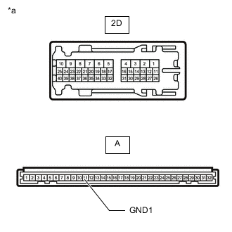
*a Component without harness connected
(Driver Side Junction Block Assembly)
Remove the driver side junction block assembly.
-
Remove the main body ECU (multiplex network body ECU) from the driver side junction block assembly.
-
Measure the resistance according to the value(s) in the table below.
Standard Resistance Tester Connection Condition Specified Condition 2D-4 - A-11 (GND1) Always Below 1 Ω A-11 (GND1) - Body ground Always Below 1 Ω
OK
REPLACE MAIN BODY ECU [MULTIPLEX NETWORK BODY ECU] Click here
NG
REPLACE DRIVER SIDE JUNCTION BLOCK ASSEMBLY Click here
-