WIPER AND WASHER SYSTEM TERMINALS OF ECU
-
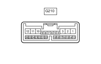
CHECK WINDSHIELD WIPER RELAY ASSEMBLY (w/ Rain Sensor)
-
Disconnect the G210 windshield wiper relay assembly connector.
-
Measure the voltage and resistance according to the value(s) in the table below.
Tech Tips
Measure the values on the wire harness side with the connector disconnected.
Terminal No. (Symbol) Wiring Color Terminal Description Condition Specified Condition G210-2 (IG) - Body ground G - Body ground IG power supply Ignition switch ON 11 to 14 V Ignition switch off Below 1 V G210-8 (VR2) - G210-21 (VR1) P - LG Adjusting volume circuit Windshield wiper switch assembly adjusting ring changed 0 to 231 Ω G210-12 (E) - Body ground W-B - Body ground Body ground Always Below 1 Ω G210-16 (WIG) - Body ground GR - Body ground IG power supply Ignition switch ON 11 to 14 V Ignition switch off Below 1 V -
Reconnect the G210 windshield wiper relay assembly connector.
-
Measure the voltage according to the value(s) in the table below.
Terminal No. (Symbol) Wiring Color Terminal Description Condition Specified Condition G210-1 (+SM) - Body ground W - Body ground Front wiper motor operation signal Front wiper motor in low or high operation 11 to 14 V Front wiper motor not operating Below 1 V G210-3 (C1) - G210-5 (C0) GR - V Front wiper switch AUTO position signal Ignition switch ON, windshield wiper switch assembly in AUTO position Below 1 V Ignition switch ON, windshield wiper switch assembly in not AUTO position 11 to 14 V G210-10 (+1) - Body ground W - Body ground Front wiper motor low speed signal Ignition switch ON, front wiper motor in low operation 11 to 14 V Ignition switch ON, front wiper motor not operating Below 1 V G210-11 (+2) - Body ground R - Body ground Front wiper motor high speed signal Ignition switch ON, front wiper motor in high operation 11 to 14 V Ignition switch ON, front wiper motor not operating Below 1 V G210-25 (W) - Body ground L - Body ground Front washer motor signal Ignition switch ON, front washer switch off 11 to 14 V Ignition switch ON, front washer switch on Below 1 V -
Measure the voltage and waveform according to the value(s) in the table below.
Terminal No. (Symbol) Wiring Color Terminal Description Condition Specified Condition G210-14 (MPX1) - Body ground P - Body ground LIN communication signal Ignition switch ON Pulse generation Ignition switch off Below 1 V G210-24 (SPD) - Body ground R - Body ground Vehicle speed signal Driving at approximately 20 km/h (12 mph) Pulse generation (See waveform 1)
-
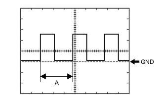
Waveform 1 (Reference):
Item Condition Tester Connection G210-24 (SPD) - Body ground Tool Setting 5 V/DIV., 20 ms./DIV. Vehicle Condition Driving at approximately 20 km/h (12 mph) Tech Tips
When the system is functioning normally, one wheel revolution generates 4 pulses. As the vehicle speed increases, the width indicated by A in the illustration narrows.
-
-
-
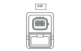
CHECK HEADLIGHT CLEANER CONTROL RELAY (w/ Headlight Cleaner System)
-
Disconnect the A38 headlight cleaner control relay connector.
-
Measure the voltage and resistance according to the value(s) in the table below.
Terminal No. (Symbol) Wiring Color Terminal Description Condition Specified Condition A38-1 (HDLO) - A38-4 (E) V - W-B Low beam headlight signal Headlight dimmer switch in head 11 to 14 V A38-1 (HDLO) - A38-4 (E) V - W-B Low beam headlight signal Headlight dimmer switch not in head Below 1 V A38-3 (IG) - A38-4 (E) L - W-B Ignition switch power supply Ignition switch ON 11 to 14 V A38-3 (IG) - A38-4 (E) L - W-B Ignition switch power supply Ignition switch off Below 1 V A38-4 (E) - Body ground W-B - Body ground Body ground Always Below 1 Ω A38-5 (FRWA) - A38-4 (E) B - W-B Front washer switch operation signal Front washer motor switch on Below 1 V A38-5 (FRWA) - A38-4 (E) B - W-B Front washer switch operation signal Front washer motor switch off 11 to 14 V
-
-
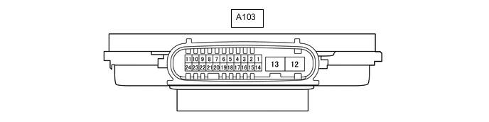
NO. 1 HEADLIGHT ECU SUB-ASSEMBLY RH (w/ Headlight Cleaner System, LED Headlight)
-
Disconnect the A103 No. 1 headlight light ECU sub-assembly RH connector.
-
Measure the resistance and voltage according to the value(s) in the table below.
Tech Tips
Measure the values on the wire harness side with the connector disconnected.
Terminal No. (Symbol) Wiring Color Terminal Description Condition Specified Condition A103-4 (IG) - Body ground GR - Body ground IG power supply Ignition switch off Below 1 V Ignition switch ON 11 to 14 V A103-12 (GND) - Body ground W-B - Body ground Body ground Always Below 1 Ω -
Reconnect the A103 No. 1 headlight light ECU sub-assembly RH connector.
-
Measure the voltage according to the value(s) in the table below.
Terminal No. (Symbol) Wiring Color Terminal Description Condition Specified Condition A103-7 (HLC) - Body ground V - Body ground Headlight cleaner motor operation signal Headlight cleaner motor not operating 11 to 14 V Headlight cleaner motor operating Below 1 V
-
-
CHECK COMBINATION METER ASSEMBLY (w/ Rain Sensor)
-
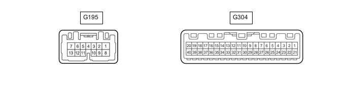
Disconnect the G304 combination meter assembly connector.
-
Measure the voltage and resistance according to the value(s) in the table below.
Tech Tips
Measure the values on the wire harness side with the connector disconnected.
Terminal No. (Symbol) Wiring Color Terminal Description Condition Specified Condition G304-21 (B) - Body ground L - Body ground Battery power supply Always 11 to 14 V G304-22 (IG+) - Body ground R - Body ground IG power supply Ignition switch ON 11 to 14 V Ignition switch off Below 1 V G304-20 (E2) - Body ground BR - Body ground Body ground Always Below 1 Ω -
Reconnect the G304 combination meter assembly connector.
-
Measure the voltage according to the value(s) in the table below.
Terminal No. (Symbol) Wiring Color Terminal Description Condition Specified Condition G304-30 (WLVL)* - Body ground W - Body ground Washer fluid level signal Ignition switch ON, washer fluid level not low 11 to 14 V Ignition switch ON, washer fluid level low Below 1 V *: w/ Washer Level Warning System
-
Measure the waveform according to the value(s) in the table below.
Terminal No. (Symbol) Wiring Color Terminal Description Condition Specified Condition G304-17 (+S) - Body ground R - Body ground Speed signal for other system (Output) Driving at approximately 20 km/h (12 mph) Pulse generation (See waveform 1)
-
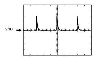
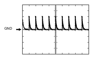
Waveform 1 (Reference):
Item Condition Tester Connection G304-17 (+S) - Body ground Tool Setting 5 V/DIV., 20 ms./DIV. Vehicle Condition Driving at approximately 20 km/h (12 mph) Tech Tips
When the system is functioning normally, one wheel revolution generates 4 pulses. As the vehicle speed increases, the width indicated by A in the illustration narrows.
-
-
-
CHECK DRIVER SIDE JUNCTION BLOCK ASSEMBLY, MAIN BODY ECU (MULTIPLEX NETWORK BODY ECU) (for 5L-E)
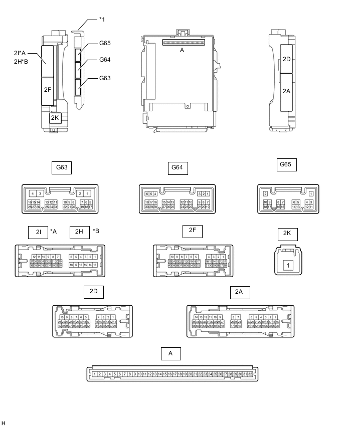
*A for LHD *B for RHD *1 Main Body ECU (Multiplex Network Body ECU) - -
-
Remove the main body ECU (multiplex network body ECU) from the driver side junction block assembly.
-
Connect the driver side junction block assembly connector.
-
Measure the voltage and resistance according to the value(s) in the table below.
Terminal No. (Symbol) Wiring Color Terminal Description Condition Specified Condition A-32 (IG) - Body ground None - Body ground IG power supply Ignition switch ON 11 to 14 V Ignition switch off Below 1 V A-31 (BECU) - Body ground None - Body ground Battery power supply Always 11 to 14 V A-30 (ACC) - Body ground None - Body ground ACC power supply Ignition switch ACC 11 to 14 V Ignition switch off Below 1 V A-11 (GND1) - Body ground None - Body ground Body ground Always Below 1 Ω G63-3 (GND2) - Body ground W-B - Body ground Body ground Always Below 1 Ω -
Install the main body ECU (multiplex network body ECU).
-
Measure the voltage and check for pulses according to the value(s) in the table below.
Terminal No. (Symbol) Wiring Color Terminal Description Condition Specified Condition G63-16 (HDLO) - G63-3 (GND2) V - W-B Low beam headlight signal Headlight dimmer switch in head 11 to 14 V Headlight dimmer switch not in head Below 1 V G63-20 (RWMR) - G63-3 (GND2) B - W-B Rear wiper power supply input Ignition switch ON, glass hatch open Below 1 V Ignition switch ON, glass hatch closed 11 to 14 V G64-1 (GCTY) - 2D-4 (GND1) V - W-B Glass hatch courtesy light switch signal Glass hatch open Below 1 V Glass hatch closed Pulse generation
(See waveform 1 or 2)
G64-6 (RCTY) - 2D-4 (GND1) R - W-B Rear door courtesy light switch RH signal Rear door RH open Below 1 V Rear door RH closed 11 to 14 V G64-19 (BCTY) - 2D-4 (GND1) G - W-B Back door courtesy light switch signal Back door open Below 1 V Back door closed Pulse generation
(See waveform 3 or 4)
G65-3 (LCTY) - 2D-4 (GND1) V - W-B Rear door courtesy light switch LH signal Rear door LH open Below 1 V Rear door LH closed 11 to 14 V
-
Waveform 1
Item Content Terminal No. (Symbol) G64-1 (GCTY) - 2D-4 (GND1) Tool setting 5 V/DIV., 20 ms./DIV. Condition Glass hatch closed -
Waveform 2
Item Content Terminal No. (Symbol) G64-1 (GCTY) - 2D-4 (GND1) Tool setting 5 V/DIV., 20 ms./DIV. Condition Glass hatch closed -
Waveform 3
Item Content Terminal No. (Symbol) G64-19 (BCTY) - 2D-4 (GND1) Tool setting 5 V/DIV., 20 ms./DIV. Condition Back door closed -
Waveform 4
Item Content Terminal No. (Symbol) G64-19 (BCTY) - 2D-4 (GND1) Tool setting 5 V/DIV., 20 ms./DIV. Condition Back door closed
-
-
-
CHECK DRIVER SIDE JUNCTION BLOCK ASSEMBLY, MAIN BODY ECU (MULTIPLEX NETWORK BODY ECU) (except 5L-E)
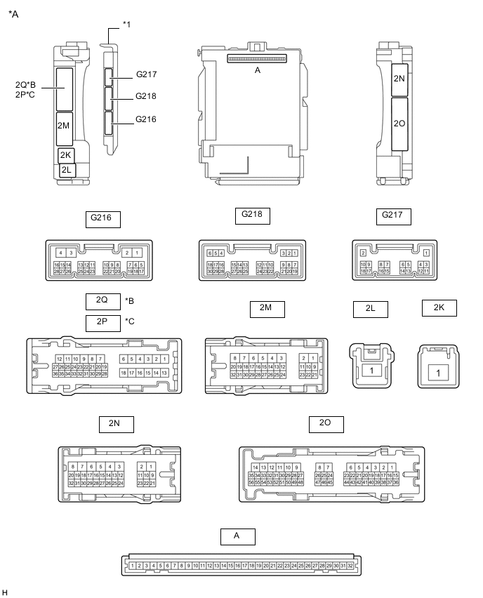
*A Main Body ECU (Multiplex Network Body ECU) with 3 connectors *B for LHD *C for RHD - - *1 Main Body ECU (Multiplex Network Body ECU) - - 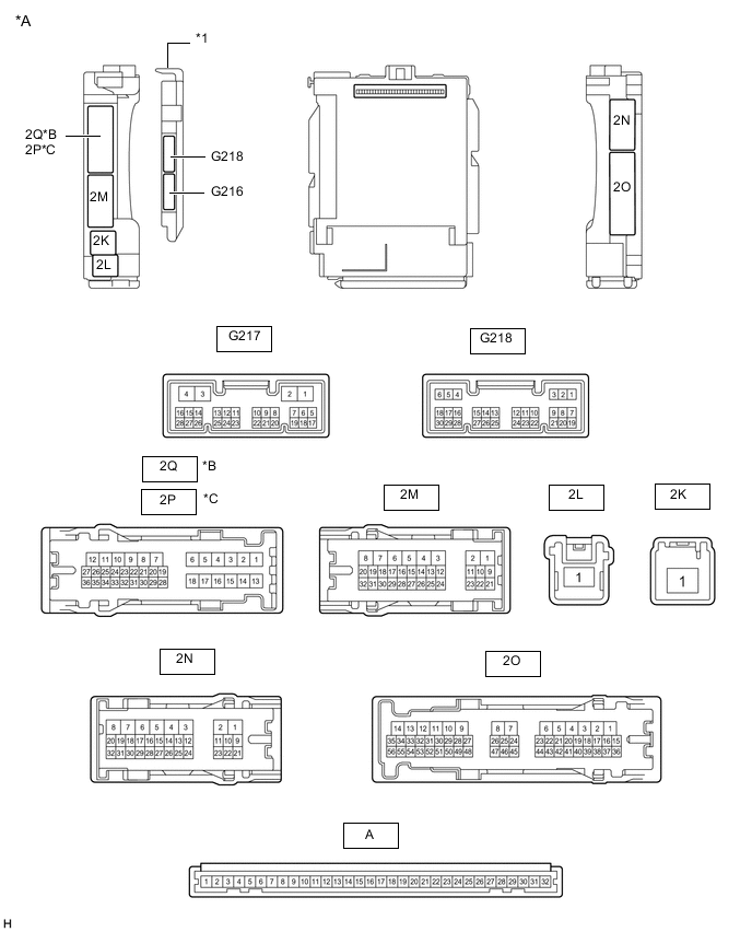
*A Main Body ECU (Multiplex Network Body ECU) with 2 connectors *B for LHD *C for RHD - - *1 Main Body ECU (Multiplex Network Body ECU) - -
-
Remove the main body ECU (multiplex network body ECU) from the driver side junction block assembly.
-
Connect the driver side junction block assembly connector.
-
Measure the voltage and resistance according to the value(s) in the table below.
Terminal No. (Symbol) Wiring Color Terminal Description Condition Specified Condition A-32 (IG) - Body ground None - Body ground IG power supply Ignition switch ON 11 to 14 V Ignition switch off Below 1 V A-31 (BECU) - Body ground None - Body ground Battery power supply Always 11 to 14 V A-30 (ACC) - Body ground None - Body ground ACC power supply Ignition switch ACC 11 to 14 V Ignition switch off Below 1 V A-11 (GND1) - Body ground None - Body ground Body ground Always Below 1 Ω -
Install the main body ECU (multiplex network body ECU).
-
Measure the voltage according to the value(s) in the table below.
Terminal No. (Symbol) Wiring Color Terminal Description Condition Specified Condition G216-19 (RWMR) - Body ground P - Body ground Rear wiper power supply input Ignition switch ON, glass hatch open Below 1 V Ignition switch ON, glass hatch closed 11 to 14 V G216-20 (WHTR) - Body ground*1 GR - Body ground Washer nozzle heater signal circuit Ignition switch ON, ambient temperature 5°C (41°F) or less Below 1 V Ignition switch ON, ambient temperature 6°C (42°F) or higher 11 to 14 V G216-27 (GCTY) - Body ground*5 V - Body ground Glass hatch courtesy light switch signal Glass hatch open Below 1 V Glass hatch closed 8 to 12 V 2N-30 (RCTY) - Body ground*2, *4
2P-23 (RCTY) - Body ground*3, *4
R - Body ground Rear door courtesy light switch RH signal Rear door RH open Below 1 V Rear door RH closed 11 to 14 V 2Q-27 (BCTY) - Body ground*2, *4
2N-27 (BCTY) - Body ground*3, *4
G - Body ground Back door courtesy light switch signal Back door open Below 1 V Back door closed 11 to 14 V 2Q-33 (LCTY) - Body ground*2, *4
2O-15 (LCTY) - Body ground*3, *4
V - Body ground Rear door courtesy light switch LH signal Rear door LH open Below 1 V Rear door LH closed 11 to 14 V *1: w/ Washer Nozzle Heater System
*2: for LHD
*3: for RHD
*4: for 5 Door
*5: w/ Glass Hatch Opener System
-