OUTER REAR VIEW MIRROR REASSEMBLY
CAUTION / NOTICE / HINT
Tech Tips
-
Use the same procedure for the RH and LH sides.
-
The procedure listed below is for the LH side.
-
w/ Multi-terrain Monitor System:
When installing only the side television camera assembly, refer to TELEVISION CAMERA (for Side)
PROCEDURE
-
INSTALL SIDE TELEVISION CAMERA ASSEMBLY (w/ Multi-terrain Monitor)
-
INSTALL OUTER MIRROR RETRACTOR LH (w/o Reverse Shift-linked Mirror)
-
Attach the 6 claws to install the 2 support springs, and then install the 2 screws.
-
Install the outer mirror actuator assembly LH.
-
Connect the connector of a new wire harness sub-assembly.
-
Install the cover and attach the 2 clamps.
-
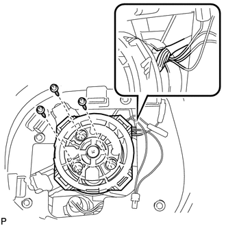
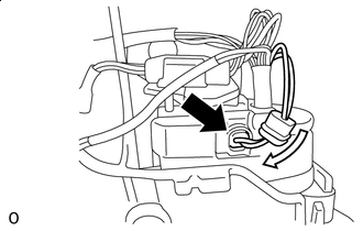
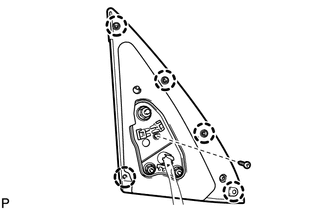
Install the outer mirror actuator assembly LH with the 3 screws.
Note
Install the outer mirror actuator assembly LH so that the wire harness sub-assembly is as shown in the illustration.
-
-
Install the wire harness sub-assembly.
-
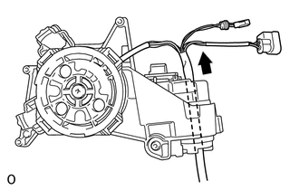
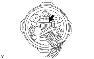
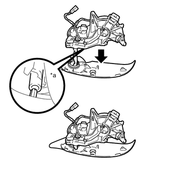
Pass a new wire harness sub-assembly through the hole in the top of a new support sub-assembly in the direction indicated by the arrow in the illustration.
-
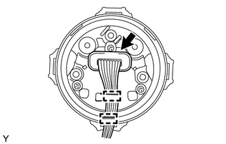
*a Cover Connect the connector and slide the cover as shown in the illustration.
-
-
Install the cover body.
-
Pass the wire harness sub-assembly through the hole in the cover body.
-
*a Guide Attach the guide as shown in the illustration to attach the cover body to the support sub-assembly.
-
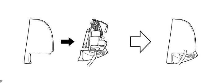
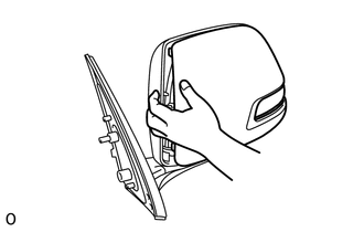
Attach the outer mirror body as shown in the illustration.
-
Install the outer mirror body with the 5 screws.
-
-
Install the cover base.
-
Pass the wire harness sub-assembly through the hole in the cover base.
-
Using a T25 "TORX" socket wrench, install the cover base with 3 new "TORX" screws.
Note
Make sure that the wire harness sub-assembly is not pinched between parts.
- Torque:
- 3.8 N*m { 39 kgf*cm, 34 in.*lbf }
-
-
Attach the 6 claws to install a new lower mirror cover.
-
Install the outer rear view mirror gasket LH.
-
Pass the wire harness sub-assembly through a new outer rear view mirror gasket LH.
-
Attach the 5 claws to install the outer rear view mirror gasket LH.
-
Install the screw.
-
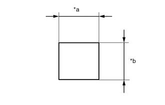
*a 50 mm (1.97 in.) *b 60 mm (2.36 in.) Prepare the 3 sizes of new vinyl tapes as in indicated the illustration.
-
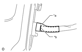
*a Tape *b Mark Align the marking of the wire harness sub-assembly with the end of the wire harness sub-assembly insertion hole on the outer rear view mirror gasket LH and secure it with vinyl tape as shown in the illustration.
Note
Apply the vinyl tape securely so there is no gap between the vinyl tape and cable.
-
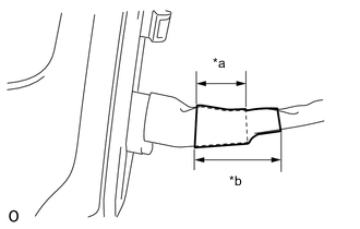
*a 30 mm (1.18 in.) *b 50 mm (1.97 in.) Apply vinyl tape in layers.
Note
Apply the tape securely so there is no gap between the vinyl tape and cable.
-
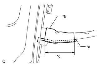
*a Clamp *b Tape *c 50 mm (1.97 in.) Secure a new clamp using vinyl tape as shown in the illustration.
-
-
Assemble the connector.
-
Wrap the longer wire harness sub-assembly around the shorter one as shown in the part of the illustration labeled (1) until they are the same length.
-
Attach the 4 claws to connect the 2 connectors to a new adapter.
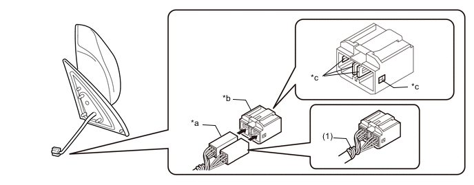
*a Connector *b Adapter *c Claw - -
-
-
-
INSTALL SIDE TURN SIGNAL LIGHT ASSEMBLY LH
-
INSTALL OUTER MIRROR COVER LH
-
Install the outer mirror cover LH.
-
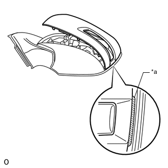
*a Rib Insert the rib on the outer edge of the outer mirror cover LH into the groove of the mirror body.
Note
Do not scratch the side turn signal light assembly LH.
-
*a Rib Confirm that the outer mirror cover LH and mirror body are aligned properly, and then push the outer end of the cover to attach the outer claws.
Note
-
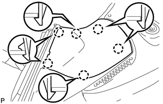
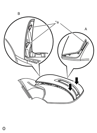
Make sure that the upper ribs of the outer mirror cover LH shown in part A of the illustration are properly attached to the mirror body.
-
Make sure that the ribs of the mirror body shown in part B of the illustration are not protruding from the outer mirror cover LH.
-
-
While making sure that the rib of the outer mirror cover LH fits properly into the groove of the mirror body, squeeze the inner end of the outer mirror cover LH and the mirror body together to attach the inner claws.
-
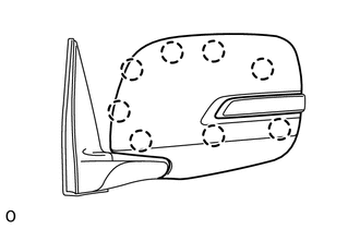
Push on the outer mirror cover LH at the locations of the 8 claws to confirm that the claws are attached properly.
-
-
-
INSTALL OUTER MIRROR GLASS