POWER MIRROR CONTROL SYSTEM(w/ Reverse Shift-linked Mirror) Power Mirror Surface Position is not Memorized
DESCRIPTION
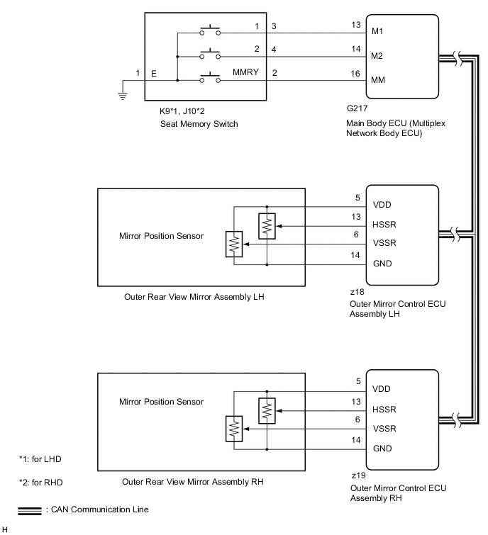
When the seat memory switch is operated, the switch input signal is sent via direct line from the outer mirror control ECU assembly LH*1 and RH*2 to the main body ECU (multiplex network body ECU). The main body ECU (multiplex network body ECU) then sends the memorization request or recall request signals to the outer mirror control ECU assembly LH and outer mirror control ECU assembly RH via CAN communication. The outer mirror control ECU assembly LH and outer mirror control ECU assembly RH memorize the mirror position when a memorization request signal is received, and move the mirror to the memorized position when a recall request signal is received.
-
*1: for LHD
-
*2: for RHD
WIRING DIAGRAM
CAUTION / NOTICE / HINT
Note
-
First perform the communication function inspections in How to Proceed with Troubleshooting to confirm that there are no CAN communication malfunctions before troubleshooting this problem.
-
If the main body ECU (multiplex network body ECU) is replaced, refer to the Service Bulletin.
-
As the door control battery is installed between the vehicle battery and main body ECU (multiplex network body ECU), first perform the inspections in On-Vehicle Inspection to confirm that there are no malfunctions in the power source circuit for the main body ECU (multiplex network body ECU) before performing this troubleshooting procedure.*
*: w/ Door Control Battery
PROCEDURE
-
READ VALUE USING GTS
-
Using the GTS, read the Data List.
-
for LH side:
Body Electrical > Mirror L > Data List Tester Display Measurement Item/Range Normal Condition Diagnostic Note Mirror Memory No.1 Mirror position memorized in memory switch M1 / OFF or ON OFF: Not memorized
ON: Memorized
- Mirror Memory No.2 Mirror position memorized in memory switch M2 / OFF or ON OFF: Not memorized
ON: Memorized
- Mirror Memory No.3 Mirror position memorized in memory switch M3 / OFF or ON OFF: Not memorized
ON: Memorized
Only item displayed (not supported) -
for RH side:
Body Electrical > Mirror R > Data List Tester Display Measurement Item/Range Normal Condition Diagnostic Note Mirror Memory No.1 Mirror position memorized in memory switch M1 / OFF or ON OFF: Not memorized
ON: Memorized
- Mirror Memory No.2 Mirror position memorized in memory switch M2 / OFF or ON OFF: Not memorized
ON: Memorized
- Mirror Memory No.3 Mirror position memorized in memory switch M3 / OFF or ON OFF: Not memorized
ON: Memorized
Only item displayed (not supported) OK The display is as specified in the normal condition column.
Result Proceed to OK NG -
NG 
INSPECT SEAT MEMORY SWITCH Click here
OK 
-
-
CHECK SEAT MEMORY SWITCH FUNCTION
-
When any seat memory switch (M1 or M2) is pressed, check that the driver seat moves to the memorized position.
OK The driver seat moves to the memorized position. Result Proceed to OK NG
NG 
GO TO FRONT POWER SEAT CONTROL SYSTEM (Power Seat does not Return to Memorized Position) Click here
OK
-
-
CHECK MEMORY AND REACTIVATION FUNCTION
-
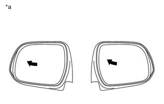
*a Turn to Fully Left Position Turn the ignition switch to ON.
-
Using the multiplex network master switch assembly, turn the mirror surface to the fully left position.
-
Press the M1 switch while the SET switch is being pressed.
-
Check that the buzzer sounds for 0.5 seconds and the mirror surface position is memorized.
-
Using the multiplex network master switch assembly, turn the mirror surface to the fully right position.
-
Press the M1 switch.
-
Check that the buzzer sounds for 0.1 seconds and the outer mirror automatically moves to the memorized fully left position.
Result Result Proceed to Memory and reactivation functions on both mirrors are not normal A Memory and reactivation functions on front door LH mirror are not normal B Memory and reactivation functions on front door RH mirror are not normal C
A
REPLACE MAIN BODY ECU (MULTIPLEX NETWORK BODY ECU) Click here
C
REPLACE OUTER REAR VIEW MIRROR ASSEMBLY RH Click here
B
-
-
REPLACE OUTER REAR VIEW MIRROR ASSEMBLY LH
-
Temporarily replace the outer rear view mirror assembly LH with a new or normally functioning one.
-
Check that the memory and reactivation function operates.
OK Memory and reactivation function operates normally. Result Proceed to NEXT
NEXT
-
-
CHECK MEMORY AND REACTIVATION FUNCTION
-
*a Turn to Fully Left Position Turn the ignition switch to ON.
-
Using the multiplex network master switch assembly, turn the mirror surface to the fully left position.
-
Press the M1 switch while the SET switch is being pressed.
-
Check that the buzzer sounds for 0.5 seconds and the mirror surface position is memorized.
-
Using the multiplex network master switch assembly, turn the mirror surface to the fully right position.
-
Press the M1 switch.
-
Check that the buzzer sounds for 0.1 seconds and the outer mirror automatically moves to the memorized fully left position.
Result Proceed to OK NG
OK
END (OUTER REAR VIEW MIRROR ASSEMBLY LH IS DEFECTIVE)
NG
REPLACE OUTER MIRROR CONTROL ECU ASSEMBLY LH Click here
-
-
REPLACE OUTER REAR VIEW MIRROR ASSEMBLY RH
-
Temporarily replace the outer rear view mirror assembly RH with a new or normally functioning one.
-
Check that the memory and reactivation function operates.
OK Memory and reactivation function operates normally. Result Proceed to NEXT
NEXT
-
-
CHECK MEMORY AND REACTIVATION FUNCTION
-
*a Turn to Fully Left Position Turn the ignition switch to ON.
-
Using the multiplex network master switch assembly, turn the mirror surface to the fully left position.
-
Press the M1 switch while the SET switch is being pressed.
-
Check that the buzzer sounds for 0.5 seconds and the mirror surface position is memorized.
-
Using the multiplex network master switch assembly, turn the mirror surface to the fully right position.
-
Press the M1 switch.
-
Check that the buzzer sounds for 0.1 seconds and the outer mirror automatically moves to the memorized fully left position.
Result Proceed to OK NG
OK
END (OUTER REAR VIEW MIRROR ASSEMBLY RH IS DEFECTIVE)
NG
REPLACE OUTER MIRROR CONTROL ECU ASSEMBLY RH Click here
-
-
INSPECT SEAT MEMORY SWITCH
-
Remove the seat memory switch.
-
Inspect the seat memory switch.
Result Proceed to OK NG
NG
REPLACE SEAT MEMORY SWITCH Click here
OK
-
-
CHECK HARNESS AND CONNECTOR (SEAT MEMORY SWITCH - MAIN BODY ECU [MULTIPLEX NETWORK BODY ECU])
-
Disconnect the G217 main body ECU (multiplex network body ECU) connector.
-
Disconnect the K9*1 or J10*2 seat memory switch connector.
-
*1: for LHD
-
*2: for RHD
-
-
Measure the resistance according to the value(s) in the table below.
Standard Resistance for LHD Tester Connection Condition Specified Condition G217-16 (MM) - K9-2 (MMRY) Always Below 1 Ω G217-16 (MM) or K9-2 (MMRY) - Body ground Always 10 kΩ or higher G217-13 (M1) - K9-3 (1) Always Below 1 Ω G217-13 (M1) or K9-3 (1) - Body ground Always 10 kΩ or higher G217-14 (M2) - K9-2 (2) Always Below 1 Ω G217-14 (M2) - K9-2 (2) - Body ground Always 10 kΩ or higher K9-1 (E) - Body ground Always Below 1 Ω for RHD Tester Connection Condition Specified Condition G217-16 (MM) - J10-2 (MMRY) Always Below 1 Ω G217-16 (MM) or J10-2 (MMRY) - Body ground Always 10 kΩ or higher G217-13 (M1) - J10-3 (1) Always Below 1 Ω G217-13 (M1) or J10-3 (1) - Body ground Always 10 kΩ or higher G217-14 (M2) - J10-2 (2) Always Below 1 Ω G217-14 (M2) - J10-2 (2) - Body ground Always 10 kΩ or higher J10-1 (E) - Body ground Always Below 1 Ω Result Proceed to OK NG
OK
REPLACE MAIN BODY ECU (MULTIPLEX NETWORK BODY ECU) Click here
NG
REPAIR OR REPLACE HARNESS OR CONNECTOR
-