POWER MIRROR CONTROL SYSTEM(w/ Reverse Shift-linked Mirror) Front Passenger Side Power Mirror cannot be Adjusted with Power Mirror Switch
DESCRIPTION
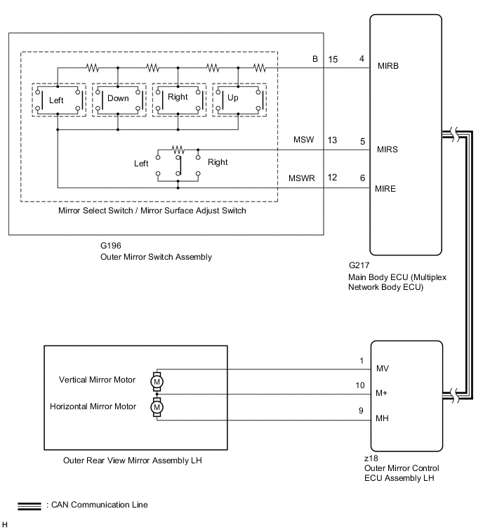
When the outer mirror switch assembly mirror surface adjust switch (up/down/left/right) is operated, up/down/left/right signals are received by the main body ECU (multiplex network body ECU). The main body ECU (multiplex network body ECU) sends the received signals to the outer mirror control ECU assembly RH*1 and LH*2 via CAN communication. The outer mirror control ECU assembly RH*1 and LH*2 receives the remote mirror selection signal and up/down/left/right signals and operates the outer rear view mirror assembly RH*1 and LH*2 up/down/left/right based on the signals.
-
*1: for LHD
-
*2: for RHD
WIRING DIAGRAM
Figure 1. for LHD:
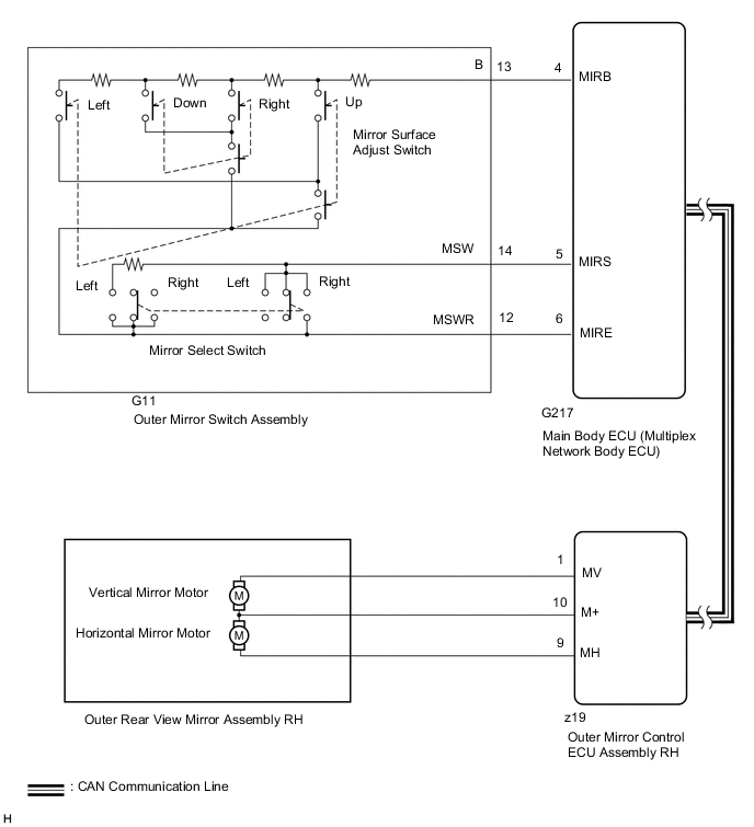
Figure 2. for RHD:
CAUTION / NOTICE / HINT
Note
-
First perform the communication function inspections in How to Proceed with Troubleshooting to confirm that there are no CAN communication malfunctions before troubleshooting this problem.
-
If the main body ECU (multiplex network body ECU) is replaced, refer to the Service Bulletin.
-
As the door control battery is installed between the vehicle battery and main body ECU (multiplex network body ECU), first perform the inspections in On-Vehicle Inspection to confirm that there are no malfunctions in the power source circuit for the main body ECU (multiplex network body ECU) before performing this troubleshooting procedure.*
*: w/ Door Control Battery
PROCEDURE
-
READ VALUE USING GTS (OUTER MIRROR SWITCH ASSEMBLY)
-
Using the GTS, read the Data List.
Body Electrical > Main Body > Data List Tester Display Measurement Item/Range Normal Condition Diagnostic Note Mirror Selection SW (R) Mirror select switch signal for RH mirror / OFF or ON OFF: Mirror select switch neutral position (off)
ON: Mirror select switch R switch on
- Mirror Selection SW (L) Mirror select switch signal for LH mirror / OFF or ON OFF: Mirror select switch neutral position (off)
ON: Mirror select switch L switch on
- Mirror Position SW (R) Mirror surface adjust switch signal (Right) / OFF or ON OFF: Mirror surface adjust switch not pressed right
ON: Mirror surface adjust switch pressed right
Check with the mirror select switch L or R switch on Mirror Position SW (L) Mirror surface adjust switch signal (Left) / OFF or ON OFF: Mirror surface adjust switch not pressed left
ON: Mirror surface adjust switch pressed left
Check with the mirror select switch L or R switch on Mirror Position SW (Up) Mirror surface adjust switch signal (Up) / OFF or ON OFF: Mirror surface adjust switch not pressed up
ON: Mirror surface adjust switch pressed up
Check with the mirror select switch L or R switch on Mirror Position SW (Dwn) Mirror surface adjust switch signal (Down) / OFF or ON OFF: Mirror surface adjust switch not pressed down
ON: Mirror surface adjust switch pressed down
Check with the mirror select switch L or R switch on OK The display is as specified in the normal condition column. Result Proceed to OK NG
NG 
INSPECT OUTER MIRROR SWITCH ASSEMBLY Click here
OK 
-
-
INSPECT OUTER REAR VIEW MIRROR ASSEMBLY (FRONT PASSENGER SIDE)
-
Remove the outer rear view mirror assembly (front passenger side).
-
Inspect the outer rear view mirror assembly (front passenger side).
Result Proceed to OK NG
OK 
REPLACE OUTER REAR VIEW MIRROR ASSEMBLY (FRONT PASSENGER SIDE) Click here
NG
REPLACE OUTER REAR VIEW MIRROR ASSEMBLY (FRONT PASSENGER SIDE) Click here
-
-
INSPECT OUTER MIRROR SWITCH ASSEMBLY
-
Remove the outer mirror switch assembly.
-
Inspect the outer mirror switch assembly.
Result Proceed to OK NG
NG
REPLACE OUTER MIRROR SWITCH ASSEMBLY Click here
OK
-
-
CHECK HARNESS AND CONNECTOR (OUTER MIRROR SWITCH ASSEMBLY - MAIN BODY ECU [MULTIPLEX NETWORK BODY ECU])
-
Disconnect the G11*1 or G196*2 outer mirror switch assembly connector.
-
*1: for LHD
-
*2: for RHD
-
-
Disconnect the G217 main body ECU (multiplex network body ECU) connector.
-
Measure the resistance according to the value(s) in the table below.
Standard Resistance for LHD Tester Connection Condition Specified Condition G11-13 (B) - G217-4 (MIRB) Always Below 1 Ω G11-14 (MSW) - G217-5 (MIRS) Always Below 1 Ω G11-12 (MSWR) - G217-6 (MIRE) Always Below 1 Ω G11-13 (B) or G217-4 (MIRB) - Body ground Always 10 kΩ or higher G11-14 (MSW) or G217-5 (MIRS) - Body ground Always 10 kΩ or higher G11-12 (MSWR) or G217-6 (MIRE) - Body ground Always 10 kΩ or higher for RHD Tester Connection Condition Specified Condition G196-15 (B) - G217-4 (MIRB) Always Below 1 Ω G196-13 (MSW) - G217-5 (MIRS) Always Below 1 Ω G196-12 (MSWR) - G217-6 (MIRE) Always Below 1 Ω G196-15 (B) or G217-4 (MIRB) - Body ground Always 10 kΩ or higher G196-13 (MSW) or G217-5 (MIRS) - Body ground Always 10 kΩ or higher G196-12 (MSWR) or G217-6 (MIRE) - Body ground Always 10 kΩ or higher Result Proceed to OK NG
OK
REPLACE MAIN BODY ECU (MULTIPLEX NETWORK BODY ECU) Click here
NG
REPAIR OR REPLACE HARNESS OR CONNECTOR
-