BACK DOOR REASSEMBLY
CAUTION / NOTICE / HINT
Tech Tips
A bolt without a torque specification is shown in the standard bolt chart Click here.
PROCEDURE
-
INSTALL LICENSE PLATE LIGHT ASSEMBLY
-
w/o Back Door Tire Carrier:
Install the license plate light assembly Click here.
-
w/ Back Door Tire Carrier:
Install the license plate light assembly Click here.
-
-
INSTALL BACK DOOR ELECTRICAL KEY SWITCH (w/ Back Door Tire Carrier)
-
INSTALL BACK DOOR ELECTRICAL KEY SWITCH (w/o Back Door Tire Carrier)
-
INSTALL REAR LICENSE LIGHT COVER
-
INSTALL NO. 1 BACK DOOR GARNISH RETAINER (w/o Back Door Tire Carrier)
-
INSTALL LICENSE PLATE LIGHT CORD (w/o Entry and Start System)
-
w/o Back Door Tire Carrier:
Install the license plate light cord Click here.
-
w/ Back Door Tire Carrier:
Install the license plate light cord Click here.
-
-
INSTALL BACK DOOR OUTSIDE GARNISH SUB-ASSEMBLY
-
w/o Back Door Tire Carrier:
Install the back door outside garnish Click here.
-
w/ Back Door Tire Carrier:
Install the back door outside garnish Click here.
-
-
INSTALL BACK DOOR LOWER DAMPER STAY BRACKET LH
-
Bumper side:
-
Install a new back door check to the back door lower damper stay bracket.
-
-
Back door side:
-
Install a new back door check to a new back door lower damper stay bracket.
-
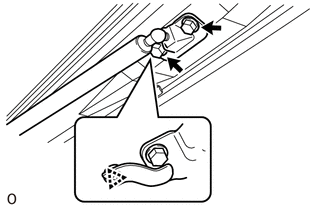
-
Check that the back door check is securely attached to the ball joint and cannot be pulled off.
-
-
INSTALL BACK DOOR CHECK
-
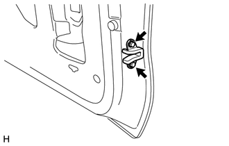
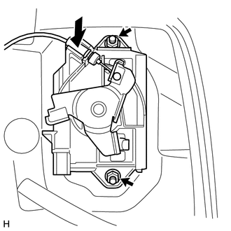
Bumper side:
-
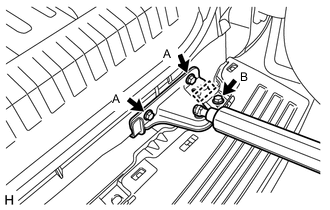
Install the back door check with back door lower damper stay bracket with the 2 bolts labeled A.
- Torque:
- 30 N*m { 306 kgf*cm, 22 ft.*lbf }
-
Install the bolt labeled B.
- Torque:
- 8.0 N*m { 82 kgf*cm, 71 in.*lbf }
-
Attach the wire harness.
-
-
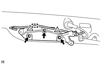
Back door side:
-
Attach the clip to install the back door check with back door lower damper stay bracket.
-
Install the 2 bolts.
- Torque:
- 30 N*m { 306 kgf*cm, 22 ft.*lbf }
-
-
-
INSTALL BACK DOOR CUSHION (w/ Back Door Tire Carrier)
-
Install the 3 back door cushions.
-
-
INSTALL BACK DOOR GLASS (w/o Back Door Tire Carrier)
-
INSTALL BACK WINDOW STAY ASSEMBLY LH (w/o Back Door Tire Carrier)
-
INSTALL BACK WINDOW STAY ASSEMBLY RH (w/o Back Door Tire Carrier)
Tech Tips
Use the same procedure described for the LH side.
-
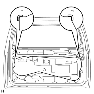
INSTALL BACK DOOR LOCK STRIKER COVER (w/o Back Door Tire Carrier)
-
When replacing the back door stay bolt with a new one:
-
Clean the threaded portion on the vehicle body with a non-residue solvent.
-
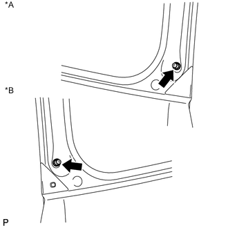
Text in Illustration *A for RH Side *B for LH Side Install the 2 back door stay bolts.
- Torque:
- 22 N*m { 224 kgf*cm, 16 ft.*lbf }
-
-
When reusing the back door stay bolt:
-
Clean the threaded portion on the vehicle body with a non-residue solvent.
-
Apply adhesive to the threads of the back door stay bolt.
Adhesive Toyota Genuine Adhesive 1324, Three Bond 1324 or equivalent -
Install the 2 back door stay bolts.
- Torque:
- 22 N*m { 224 kgf*cm, 16 ft.*lbf }
-
-
-
INSTALL NO. 1 BACK WINDOW WIPER MOTOR BRACKET (w/ Back Door Tire Carrier)
-
Attach the 2 clips to install the No. 1 back window wiper motor bracket.
-
Install the 3 bolts.
-
Attach the washer hose clamp.
-
-
INSTALL REAR WIPER MOTOR ASSEMBLY
-
INSTALL REAR WIPER ARM
-
INSTALL REAR WASHER NOZZLE SUB-ASSEMBLY
-
INSTALL NO. 2 BACK DOOR STIFFENER (w/ Back Door Tire Carrier)
-
INSTALL REAR SPOILER SUB-ASSEMBLY
-
w/o Back Door Tire Carrier:
Install the rear spoiler sub-assembly Click here.
-
w/ Back Door Tire Carrier:
Install the rear spoiler sub-assembly Click here.
-
-
INSTALL REAR SPOILER COVER RH
-
INSTALL REAR NO. 1 SPOILER COVER (w/o Back Door Tire Carrier)
-
INSTALL BACK WINDOW LOCK ASSEMBLY (w/o Back Door Tire Carrier)
-
INSTALL BACK DOOR PANEL CUSHION (w/o Back Door Tire Carrier)
-
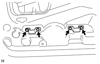
Install the 4 back door panel cushions.
-
-
INSTALL BACK DOOR NO. 1 STOPPER
-
Attach the 2 claws to install a new back door No. 1 stopper.
-
-
INSTALL BACK DOOR NO. 2 STOPPER CUSHION
-
Attach the claw to install the back door No. 2 stopper cushion.
-
-
INSTALL BACK DOOR SIDE FEMALE STOPPER SUB-ASSEMBLY LH
-
Install the back door side female stopper sub-assembly with the 2 bolts .
- Torque:
- 7.0 N*m { 71 kgf*cm, 62 in.*lbf }
-
-
INSTALL NO. 2 BACK DOOR WEATHERSTRIP (w/o Back Door Tire Carrier)
-
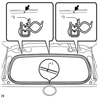
Text in Illustration *1 Joint of Weatherstrip *2 Paint Mark (White) *3 Paint Mark (Light Blue) Align the alignment mark on the weatherstrip with the protruding portion on the body indicated by the arrow in the illustration and install the No. 2 back door weatherstrip.
Note
After installation, check that the corners fit correctly.
-
-
INSTALL SWITCH COVER (w/o Back Door Tire Carrier)
-
INSTALL GLASS HATCH OPENER SWITCH ASSEMBLY (w/o Back Door Tire Carrier)
-
INSTALL LOWER BACK DOOR GARNISH SUB-ASSEMBLY OUTSIDE LH (w/o Back Door Tire Carrier)
-
INSTALL LOWER BACK DOOR GARNISH SUB-ASSEMBLY OUTSIDE RH (w/o Back Door Tire Carrier)
-
Clean the vehicle body surface.
-
Using a heat light, heat the vehicle body surface.
Heating Temperature Item Temperature Vehicle body 40 to 60°C (104 to 140°F) Note
Do not heat the vehicle body excessively.
-
Wipe off any tape adhesive residue with cleaner.
-
-
Install a new rear lower back door garnish sub-assembly outside RH.
-
Using a heat light, heat the vehicle body and a new rear lower back door garnish sub-assembly outside RH.
-
Remove the release paper from the face of the rear lower back door garnish sub-assembly outside RH.
Tech Tips
After removing the release paper, keep the exposed adhesive free from foreign matter.
-
-
Attach the 4 claws to install the rear lower back door garnish sub-assembly outside RH, and then install the screw.
-
-
INSTALL LOWER BACK DOOR OUTSIDE GARNISH MOULDING LH (w/o Back Door Tire Carrier)
-
INSTALL LOWER BACK DOOR OUTSIDE GARNISH MOULDING RH (w/o Back Door Tire Carrier)
-
Attach the 5 claws to install the lower back door outside garnish moulding RH.
-
-
INSTALL NO. 2 BACK DOOR GARNISH RETAINER (w/o Back Door Tire Carrier, w/o Rear View Monitor System)
-
Install the No. 2 back door garnish retainer to the door panel with the 2 screws.
-
-
INSTALL REAR TELEVISION CAMERA ASSEMBLY (w/o Back Door Tire Carrier, w/ Rear View Monitor System)
-
INSTALL REAR NO. 1 WINDOW WIRE (w/ Back Door Tire Carrier, w/ Rear View Monitor System)
-
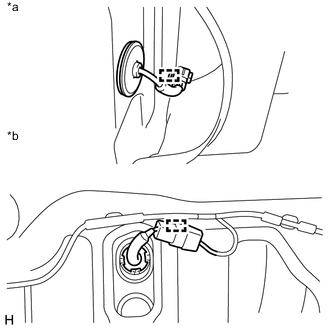
Text in Illustration *a Outer Side *b Inner Side Attach the 2 clamps to install the rear No. 1 window wire.
-
Connect the connector.
-
-
INSTALL BACK DOOR LOCK CONTROL CABLE ASSEMBLY
-
Install the cable.
-
-
INSTALL BACK DOOR LOCK ASSEMBLY
-
INSTALL BACK DOOR OUTSIDE HANDLE LH
-
w/ Back Door Tire Carrier:
-
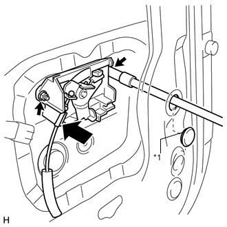
Text in Illustration *1 Hole Plug Connect the cable.
-
Install the back door outside handle with the 2 nuts.
- Torque:
- 5.0 N*m { 51 kgf*cm, 44 in.*lbf }
-
Install the hole plug.
-
-
w/o Back Door Tire Carrier:
-
Connect the cable.
-
Install the back door outside handle with the 2 nuts.
- Torque:
- 5.0 N*m { 51 kgf*cm, 44 in.*lbf }
-
-
-
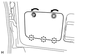
INSTALL BACK DOOR SERVICE HOLE COVER
-
Text in Illustration *1 Reference Point Apply new butyl tape to the back door panel.
-
Attach the rear door service hole cover using to the reference points on the rear door panel.
Note
-
There should be no wrinkles or folds after attaching the service hole cover.
-
After attaching the service hole cover, check the seal quality.
-
-
-
INSTALL TOOL BOX BRACKET
-
Install the 2 tool box brackets with the 4 bolts.
-
-
INSTALL BACK DOOR INSIDE HANDLE SUB-ASSEMBLY (for Face to Face Seat Type)
-

Connect the 2 cables to the inside handle sub-assembly.
-
Attach the claws and guide to install the inside handle sub-assembly.
-
-
INSTALL BACK DOOR TRIM PANEL ASSEMBLY
-
w/o Back Door Tire Carrier:
-
Attach the 15 clips to install the back door trim panel assembly.
-
Install the bolt.
-
-
w/ Back Door Tire Carrier:
-
Attach the 16 clips to install the back door trim panel assembly.
-
Install the bolt.
-
-
for Face to Face Seat Type:
-
Attach the 15 clips to install the back door trim panel assembly.
-
Install the bolt.
-
-
Install the screw.
-
Attach the claw to install the cover.
-
-
INSTALL BACK DOOR INSIDE HANDLE BEZEL (for Face to Face Seat Type)
-
Attach the 5 claws to install the back door inside handle bezel.
-
Install the screw.
-
-
INSTALL BACK DOOR LOCK COVER (w/o Back Door Tire Carrier)
-
Attach the 6 claws to install the back door lock cover.
-
-
INSTALL TOOL CASE
-
Attach the 2 claws to install the tool case.
-
-
INSTALL UPPER TOOL BOX PANEL SUB-ASSEMBLY
-
Attach the 3 claws.
-
Install the upper tool box panel sub-assembly as shown in the illustration.
-
-
INSTALL BACK DOOR TRIM COVER
-
Attach the 4 claws.
-
Install the back door trim cover as shown in the illustration.
-
-
INSTALL BACK DOOR SIDE GARNISH LH
-
Attach the 2 clips and claw to install the back door side garnish.
-
-
INSTALL BACK DOOR SIDE GARNISH RH
-
Attach the 2 clips and claw to install the back door side garnish.
-
-
INSTALL BACK DOOR CENTER GARNISH
-
Attach the 4 clips to install the back door center garnish.
-
-
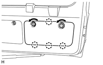
INSTALL SPARE WHEEL CARRIER BRACKET SUB-ASSEMBLY (w/ Back Door Tire Carrier)
-
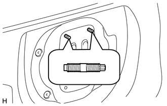
Using an E10 "TORX" socket wrench, install the 2 stud bolts.
- Torque:
- 42 N*m { 428 kgf*cm, 31 ft.*lbf }
-
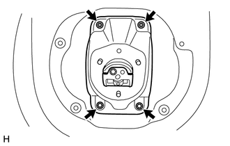
Install the spare wheel carrier bracket sub-assembly with the 2 bolts and 2 nuts.
- Torque:
- 48 N*m { 489 kgf*cm, 35 ft.*lbf }
- for bolt and nut
-
-
INSTALL REAR TELEVISION CAMERA ASSEMBLY (w/ Back Door Tire Carrier, w/ Rear View Monitor System)
-
INSTALL TELEVISION CAMERA BRACKET (w/ Back Door Tire Carrier, w/o Rear View Monitor System)
-
INSTALL NO. 2 SPARE WHEEL COVER (w/ Back Door Tire Carrier)
-
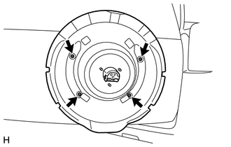
Install the No. 2 spare wheel cover with the 4 screws.
-
-
INSTALL SPARE TIRE (w/ Back Door Tire Carrier)
-
INSTALL SPARE WHEEL COVER (w/ Back Door Tire Carrier)
-
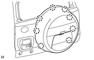
Attach the 8 claws to install the spare wheel cover.
-
Move the lever.
-
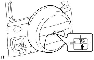
Install the bolt.
- Torque:
- 14 N*m { 143 kgf*cm, 10 ft.*lbf }
-
-
INSTALL SPARE WHEEL COVER PAD (w/ Back Door Tire Carrier)
-
Attach the 7 claws to install the wheel cover pad.
-