FRONT DOOR REASSEMBLY

CAUTION / NOTICE / HINT
Tech Tips
-
Use the same procedure for RHD and LHD vehicles.
-
The procedure listed below is for LHD vehicles.
-
Use the same procedure for the RH and LH sides.
-
The procedure listed below is for the LH side.
-
A bolt without a torque specification is shown in the standard bolt chart.
PROCEDURE
-
INSTALL BACK DOOR CUSHION
-
Attach the clip to install a new door panel cushion.
-
-
REPAIR INSTRUCTION
-
INSTALL NO. 2 FRONT DOOR STRIPE LH
-
INSTALL FRONT DOOR OUTSIDE STRIPE LH
-
INSTALL NO. 1 BLACK OUT TAPE LH
-
INSTALL FRONT DOOR REAR WINDOW FRAME MOULDING LH
-
INSTALL FRONT DOOR BELT MOULDING LH
-
INSTALL FRONT DOOR WEATHERSTRIP LH
-
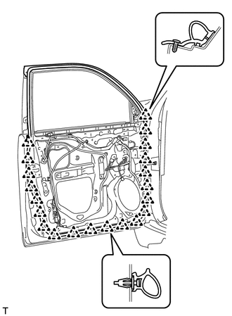
Attach the 21 clips to install a new front door weatherstrip LH.
-
-
INSTALL FRONT DOOR CHECK ASSEMBLY LH
-
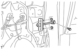
Install the front door check assembly LH to the front door panel assembly with the 2 nuts.
- Torque:
- 8.0 N*m { 82 kgf*cm, 71 in.*lbf }
-
Apply adhesive to the threads of the bolt.
Adhesive Toyota Genuine Adhesive 1324, Three Bond 1324 or equivalent -
Install the front door check assembly LH with the bolt.
- Torque:
- 27 N*m { 275 kgf*cm, 20 ft.*lbf }
-
-
INSTALL FRONT DOOR NO. 2 STIFFENER CUSHION
-
Clean the installation surface.
-
Using a heat light, heat the installation surface.
Standard Item Temperature Vehicle body 40 to 60°C (104 to 140°F) Note
Do not heat the vehicle body excessively.
-
Remove the double-sided tape from the installation surface.
-
Wipe off any tape adhesive residue with cleaner.
-
-
Install a new front door No. 2 stiffener cushion.
-
Using a heat light, heat the front door No. 2 stiffener cushion and the installation surface.
Tech Tips
When installing the front door No. 2 stiffener cushion, heat the vehicle body and door stiffener cushion using a heat light.
Standard Item Temperature Door stiffener cushion 20 to 30°C (68 to 86°F) Vehicle body 40 to 60°C (104 to 140°F) Note
Do not heat the front door No. 2 stiffener cushion and vehicle body excessively.
-
Remove the peeling paper from the face of the front door No. 2 stiffener cushion.
Tech Tips
After removing the peeling paper, keep the exposed adhesive free from foreign matter.
-
Attach the 2 clamps and double-sided tape to install the front door No. 2 stiffener cushion.
Tech Tips
Press the front door No. 2 stiffener cushion firmly to install it.
-
Install the 2 bolts.
-
-
-
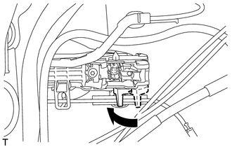
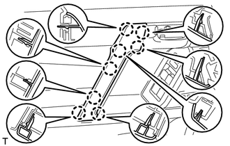
INSTALL FRONT DOOR LOCK OPEN ROD LH
-
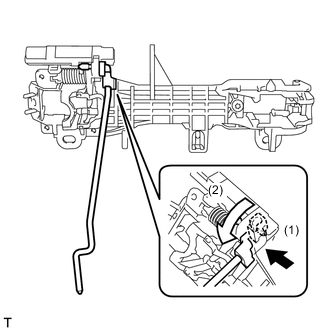
Install the front door lock open rod LH as indicated by the arrows in the order shown in the illustration.
-
-
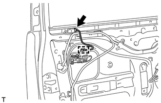
INSTALL FRONT DOOR WIRE LH (w/ Smart Entry and Start System)
-
Attach the 4 clamps to install the front door wire LH.
-
-
INSTALL FRONT DOOR OUTSIDE HANDLE FRAME SUB-ASSEMBLY LH
-
Apply MP grease to the sliding parts of the front door outside handle frame sub-assembly LH.
-
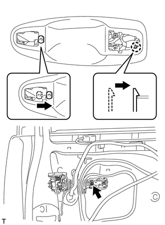
Attach the door handle nut and claw.
-
Using a T30 "TORX" socket wrench, install the front door outside handle frame sub-assembly LH with the screw.
- Torque:
- 4.0 N*m { 41 kgf*cm, 35 in.*lbf }
-
w/ Entry and Start System:
-
Attach the clamp.
-
Connect the front door wire LH connector.
-
-
-
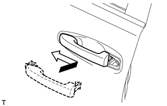
INSTALL FRONT DOOR REAR OUTSIDE HANDLE PAD LH
-
Attach the 2 claws to install the front door rear outside handle pad LH.
-
-
INSTALL FRONT DOOR FRONT OUTSIDE HANDLE PAD LH
-
Attach the 3 claws to install the front door front outside handle pad LH.
-
-
INSTALL FRONT DOOR OUTSIDE HANDLE ASSEMBLY LH
-
Insert the front end of the front door outside handle assembly LH into the front door outside handle frame sub-assembly LH.
-
Insert the rear end of the front door outside handle assembly LH into the front door outside handle frame sub-assembly LH, and then slide the front door outside handle assembly LH toward the front of the vehicle to install it.
-
Move the lever in the direction indicated by the arrow in the illustration to lock the front door outside handle assembly LH.
-
Connect the connector.
-
Attach the 2 claws.
-
-
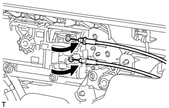
INSTALL FRONT DOOR INSIDE LOCKING CABLE ASSEMBLY LH
-
Install the front door inside locking cable assembly LH.
-
Attach the 3 claws.
-
-
INSTALL FRONT DOOR LOCK REMOTE CONTROL CABLE ASSEMBLY LH
-
Install the front door lock remote control cable assembly LH.
-
-
INSTALL FRONT DOOR LOCK ASSEMBLY LH
-
INSTALL FRONT DOOR OUTSIDE HANDLE COVER RH (for Front Passenger Side)
-
Using a T30 "TORX" socket wrench, install the front door outside handle cover RH with the screw.
- Torque:
- 4.0 N*m { 41 kgf*cm, 35 in.*lbf }
-
Install the hole plug.
-
-
INSTALL FRONT DOOR OUTSIDE HANDLE COVER LH (for Driver Side)
-
Attach the claw to install the front door outside handle cover LH to the lock cylinder assembly.
-
-
INSTALL FRONT DOOR OUTSIDE HANDLE COVER WITH LOCK CYLINDER ASSEMBLY (for Driver Side)
-
Install the front door outside handle cover with lock cylinder assembly.
Tech Tips
Make sure that the door lock cylinder rod is inserted into the front door lock assembly LH.
-
Using a T30 "TORX" socket wrench, install the front door outside handle cover with lock cylinder assembly with the screw.
- Torque:
- 4.0 N*m { 41 kgf*cm, 35 in.*lbf }
-
Install the hole plug.
-
-
INSTALL FRONT DOOR REAR LOWER FRAME SUB-ASSEMBLY LH
-
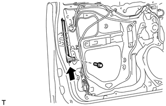
Install the front door rear lower frame sub-assembly LH with the bolt as shown in the illustration.
-
-
INSTALL DOOR FRAME GARNISH LH
-
Attach the clip to install a new door frame garnish LH.
-
-
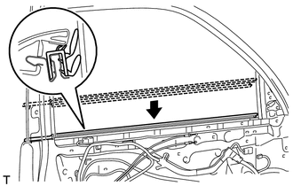
INSTALL FRONT DOOR GLASS RUN LH
-
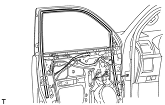
Install the front door glass run LH.
-
-
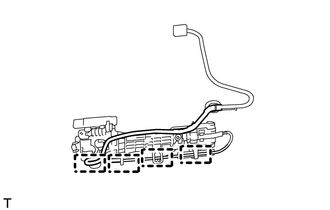
INSTALL POWER WINDOW REGULATOR MOTOR ASSEMBLY LH
-
INSTALL FRONT DOOR WINDOW REGULATOR SUB-ASSEMBLY LH
-
Apply MP grease to the sliding parts of the front door window regulator sub-assembly LH.
-
Install the temporary bolt to the front door window regulator sub-assembly LH.
-
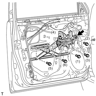
*1 Temporary Bolt Temporarily install the front door window regulator sub-assembly LH with the temporary bolt.
-
Temporarily install the 5 bolts, and then tighten the temporary bolt and 5 bolts.
- Torque:
- 8.0 N*m { 82 kgf*cm, 71 in.*lbf }
Tech Tips
Tighten the bolts in the order shown in the illustration.
-
Connect the connector.
-
-
INSTALL FRONT DOOR GLASS SUB-ASSEMBLY LH
-
Connect the cable to the negative (-) battery terminal.
-
Connect the multiplex network master switch assembly and move the front door glass sub-assembly LH so that the door glass bolt installation locations can be seen.
-
Disconnect the cable from the negative (-) battery terminal and multiplex network master switch assembly.
CAUTION:
Wait at least 90 seconds after disconnecting the cable from the negative (-) battery terminal to disable the SRS system.
-
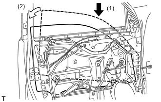
Insert the front door glass sub-assembly LH into the front door panel along the front door glass run LH as indicated by the arrows in the order shown in the illustration.
-
Install the front door glass sub-assembly LH with the 2 bolts.
- Torque:
- 8.0 N*m { 82 kgf*cm, 71 in.*lbf }
Tech Tips
Tighten the bolts in the order shown in the illustration.
-
-
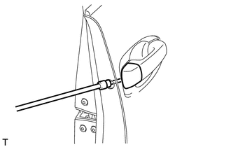
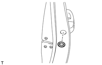
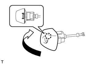
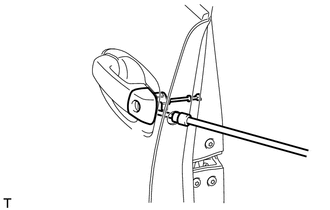
INSTALL OUTER REAR VIEW MIRROR ASSEMBLY LH
-
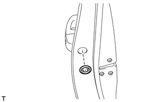
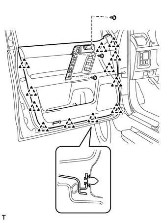
INSTALL FRONT DOOR SERVICE HOLE COVER LH
-
Apply new butyl tape to the front door panel assembly LH.
-
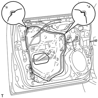
*a Reference Point Pass the front door lock remote control cable assembly LH and front door inside locking cable assembly LH through a new front door service hole cover LH.
-
Attach the front door service hole cover LH using the reference points on the front door panel assembly LH.
Note
-
There should be no wrinkles or folds after attaching the front door service hole cover LH.
-
After attaching the front door service hole cover LH, check the seal quality.
Note
Securely install the front door service hole cover LH preventing wrinkles and air bubbles.
-
-
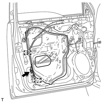
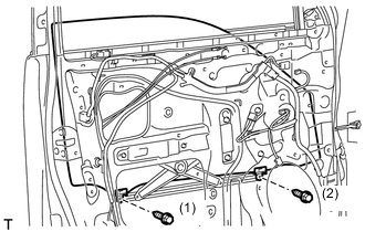
Attach the 2 clamps.
-
Install the bolt to the front door wire LH.
-
-
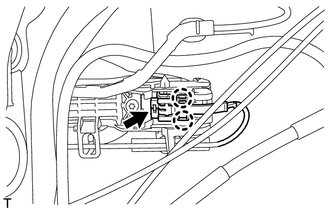
INSTALL SIDE AIRBAG SENSOR ASSEMBLY LH
-
INSTALL FRONT NO. 1 SPEAKER ASSEMBLY
-
INSTALL OUTER MIRROR CONTROL ECU ASSEMBLY LH (w/ Reverse Shift-linked Mirror)
-
INSTALL SEAT MEMORY SWITCH (w/ Seat Position Memory System)
-
INSTALL FRONT DOOR INSIDE HANDLE SUB-ASSEMBLY LH
-
Attach the guide and 2 claws to install the front door inside handle sub-assembly LH to the front door trim board sub-assembly LH.
-
Install the 2 screws.
-
Install the 8 screws to the door assist grip assembly LH.
-
-
INSTALL POWER WINDOW REGULATOR SWITCH ASSEMBLY (for Front Passenger Side)
-
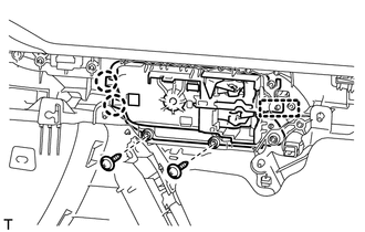
INSTALL MULTIPLEX NETWORK MASTER SWITCH ASSEMBLY (for Driver Side)
-
Install the multiplex network master switch assembly with the 3 screws.
-
-
INSTALL FRONT DOOR INSIDE HANDLE ILLUMINATION LIGHT ASSEMBLY LH (w/ Personal Light)
-
INSTALL NO. 1 INTERIOR ILLUMINATION LIGHT ASSEMBLY LH (w/ Personal Light)
-
INSTALL FRONT REFLEX REFLECTOR ASSEMBLY
-
Attach the 2 claws to install the front reflex reflector assembly.
-
-
INSTALL FRONT DOOR INNER GLASS WEATHERSTRIP LH
-
Install the front door inner glass weatherstrip LH.
-
-
INSTALL FRONT DOOR TRIM BOARD SUB-ASSEMBLY LH
-
Connect the front door lock remote control cable assembly LH and front door inside locking cable assembly LH.
-
Connect the 2 connectors.
-
w/ Seat Position Memory System:
-
Connect the connectors.
-
-
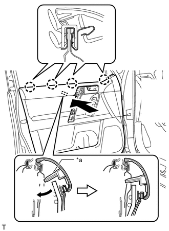
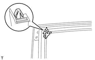
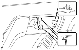
*a Reference Boss Attach the reference boss and front door trim board sub-assembly LH by attaching the 4 claws of the front door inner glass weatherstrip LH as shown in the illustration.
-
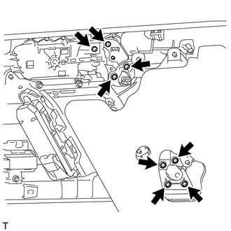
Attach the 12 clips to install the front door trim board sub-assembly LH.
-
Install the 3 screws.
-
-
INSTALL ASSIST GRIP COVER LH
-
Attach the 8 claws to install the assist grip cover LH.
-
-
INSTALL NO. 2 DOOR INSIDE HANDLE BEZEL LH
-
Attach the 3 claws to install the No. 2 door inside handle bezel LH.
-
-
INSTALL FRONT DOOR LOWER FRAME BRACKET GARNISH LH
-
Attach the 2 claws to install the front door lower frame bracket garnish LH.
-
-
CONNECT CABLE TO NEGATIVE BATTERY TERMINAL
Note
When disconnecting the cable, some systems need to be initialized after the cable is reconnected.
-
INITIALIZE POWER WINDOW CONTROL SYSTEM
-
Initialize the power window.
-
-
CHECK SRS WARNING LIGHT
-
Check the SRS warning light.
-
-
ADJUST SIDE TELEVISION CAMERA ASSEMBLY (w/ Side Monitor System)