SLIDING ROOF SYSTEM TERMINALS OF ECU
-
CHECK SLIDING ROOF DRIVE GEAR SUB-ASSEMBLY (SLIDING ROOF ECU)
-
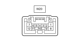
Disconnect the W20 sliding roof drive gear sub-assembly (sliding roof ECU) connector.
-
Measure the resistance and voltage according to the value(s) in the table below.
Tester Connection Wiring Color Terminal Description Condition Specified Condition W20-1 (IG) - Body ground L - Body ground IG power supply Ignition switch off Below 1 V Ignition switch ON 11 to 14 V W20-4 (UP) - Body ground R - Body ground Slide roof switch up signal Ignition switch ON, sliding roof tilted downward Tilt up switch on → off 1 kΩ or higher → Below 100 Ω W20-5 (CLS) - Body ground B - Body ground Slide roof switch close signal Ignition switch ON, sliding roof open Slide close switch on → off 1 kΩ or higher → Below 100 Ω W20-6 (DWN) - Body ground P - Body ground Slide roof switch down signal Ignition switch ON, sliding roof tilted upward Tilt down switch on → off 1 kΩ or higher → Below 100 Ω W20-7 (OPN) - Body ground LG - Body ground Slide roof switch open signal Ignition switch ON, sliding roof closed Slide open switch on → off 1 kΩ or higher → Below 100 Ω W20-8 (B) - Body ground W - Body ground Battery power supply Always 11 to 14 V W20-12 (E) - Body ground W-B - Body ground Ground Always Below 1 Ω
-
-
CHECK DRIVER SIDE JUNCTION BLOCK ASSEMBLY AND MAIN BODY ECU (MULTIPLEX NETWORK BODY ECU) (for 5L-E)
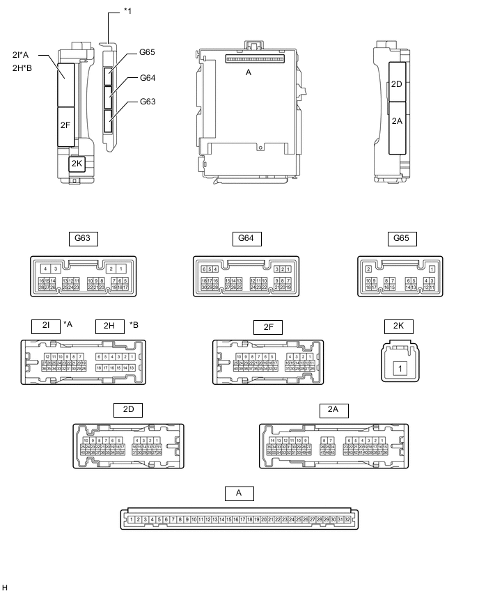
*A for LHD *B for RHD *1 Main Body ECU (Multiplex Network Body ECU) - -
-
Remove the main body ECU (multiplex network body ECU) from the driver side junction block assembly.
-
Measure the voltage and resistance according to the value(s) in the table below.
Terminal No. (Symbol) Wiring Color Terminal Description Condition Specified Condition A-30 (BECU) - Body ground - Battery power supply Always 11 to 14 V A-31 (ALTB) - Body ground - Battery power supply Always 11 to 14 V A-32 (IG) - Body ground - Ignition switch power supply Ignition switch ON 11 to 14 V A-32 (IG) - Body ground - Ignition switch power supply Ignition switch off Below 1 V A-29 (ACC) - Body ground - ACC power supply Ignition switch ACC 11 to 14 V A-29 (ACC) - Body ground - ACC power supply Ignition switch off Below 1 V A-11 (GND1) - Body ground - Ground Always Below 1 Ω G63-3 (GND2) - Body ground W-B - Body ground Ground Always Below 1 Ω -
Install the main body ECU (multiplex network body ECU).
-
Measure the voltage according to the value(s) in the table below.
for LHD: Terminal No. (Symbol) Wiring Color Terminal Description Condition Specified Condition 2I-27 (FLCY) - Body ground R - Body ground Front door LH courtesy switch input Front door LH open Below 1 V 2I-27 (FLCY) - Body ground R - Body ground Front door LH courtesy switch input Front door LH closed 11 to 14 V G64-11 (L2) - Body ground GR - Body ground Driver side door key-linked lock input Driver side door key cylinder in lock position Below 1 V G64-11 (L2) - Body ground GR - Body ground Driver side door key-linked lock input Ignition switch off, all doors closed and driver side door key cylinder in neutral position Pulse generation G64-24 (UL3) - Body ground LG - Body ground Driver side door key-linked unlock input Driver side door key cylinder in unlock position Below 1 V G64-24 (UL3) - Body ground LG - Body ground Driver side door key-linked unlock input Ignition switch off, all doors closed and driver side door key cylinder in neutral position Pulse generation G64-26 (RDA) - Body ground P - Body ground Door control receiver input No key in ignition key cylinder, all doors closed and transmitter switch off → on 11 to 14 V → Pulse generation for RHD: Terminal No. (Symbol) Wiring Color Terminal Description Condition Specified Condition 2H-26 (FRCY) - Body ground B - Body ground Front door RH courtesy switch input Front door RH open Below 1 V 2H-26 (FRCY) - Body ground B - Body ground Front door RH courtesy switch input Front door RH closed 11 to 14 V G64-11 (L2) - Body ground GR - Body ground Driver side door key-linked lock input Driver side door key cylinder in lock position Below 1 V G64-11 (L2) - Body ground GR - Body ground Driver side door key-linked lock input Ignition switch off, all doors closed and driver side door key cylinder in neutral position Pulse generation G64-24 (UL3) - Body ground LG - Body ground Driver side door key-linked unlock input Driver side door key cylinder in unlock position Below 1 V G64-24 (UL3) - Body ground LG - Body ground Driver side door key-linked unlock input Ignition switch off, all doors closed and driver side door key cylinder in neutral position Pulse generation G64-26 (RDA) - Body ground P - Body ground Door control receiver input No key in ignition key cylinder, all doors closed and transmitter switch off → on 11 to 14 V → Pulse generation
-
-
CHECK DRIVER SIDE JUNCTION BLOCK ASSEMBLY AND MAIN BODY ECU (MULTIPLEX NETWORK BODY ECU) (except 5L-E)
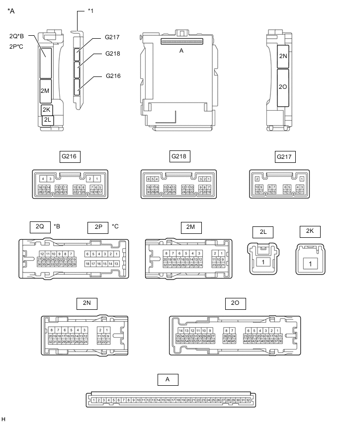
*A Main Body ECU (Multiplex Network Body ECU) with 3 connectors *B for LHD *C for RHD - - *1 Main Body ECU (Multiplex Network Body ECU) - - 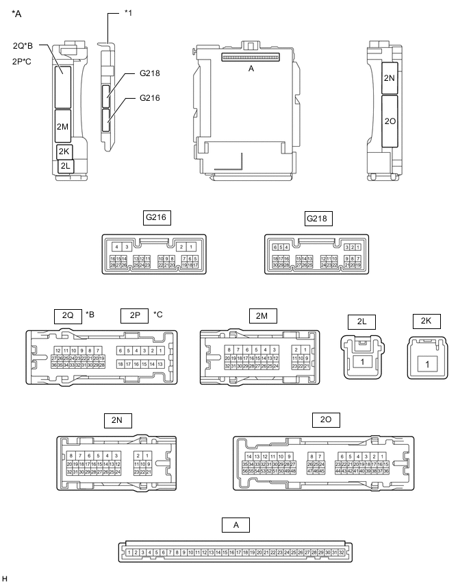
*A Main Body ECU (Multiplex Network Body ECU) with 2 connectors *B for LHD *C for RHD - - *1 Main Body ECU (Multiplex Network Body ECU) - -
-
Remove the main body ECU (multiplex network body ECU) from the driver side junction block assembly.
-
Measure the voltage and resistance according to the value(s) in the table below.
Terminal No. (Symbol) Wiring Color Terminal Description Condition Specified Condition A-31 (BECU) - Body ground - Battery power supply Always 11 to 14 V A-32 (IG) - Body ground - Ignition switch power supply Ignition switch ON 11 to 14 V A-32 (IG) - Body ground - Ignition switch power supply Ignition switch off Below 1 V A-30 (ACC) - Body ground - ACC power supply Ignition switch ACC 11 to 14 V A-30 (ACC) - Body ground - ACC power supply Ignition switch off Below 1 V A-11 (GND1) - Body ground - Ground Always Below 1 Ω -
Install the main body ECU (multiplex network body ECU).
-
Measure the voltage according to the value(s) in the table below.
for LHD: Terminal No. (Symbol) Wiring Color Terminal Description Condition Specified Condition G218-6 (FLCY) - Body ground R - Body ground Front door LH courtesy switch input Front door LH open Below 1 V G218-6 (FLCY) - Body ground R - Body ground Front door LH courtesy switch input Front door LH closed Pulse generation G218-29 (L2) - Body ground GR - Body ground Driver side door key-linked lock input Driver side door key cylinder in lock position Below 1 V G218-29 (L2) - Body ground GR - Body ground Driver side door key-linked lock input Ignition switch off, all doors closed and driver side door key cylinder in neutral position Pulse generation G218-2 (UL3) - Body ground LG - Body ground Driver side door key-linked unlock input Driver side door key cylinder in unlock position Below 1 V G218-2 (UL3) - Body ground LG - Body ground Driver side door key-linked unlock input Ignition switch off, all doors closed and driver side door key cylinder in neutral position Pulse generation G218-4 (RDA) - Body ground*1 P - Body ground*2
B - Body ground*3
Signal input from door control receiver Ignition switch off, all doors closed and door control transmitter assembly switch not pressed 11 to 14 V G218-4 (RDA) - Body ground*1 P - Body ground*2
B - Body ground*3
Signal input from door control receiver Ignition switch off, all doors closed and door control transmitter assembly switch pressed Pulse generation for RHD: Terminal No. (Symbol) Wiring Color Terminal Description Condition Specified Condition G218-27 (FRCY) - Body ground B - Body ground Front door RH courtesy switch input Front door RH open Below 1 V G218-27 (FRCY) - Body ground B - Body ground Front door RH courtesy switch input Front door RH closed Pulse generation G218-29 (L2) - Body ground GR - Body ground Driver side door key-linked lock input Driver side door key cylinder in lock position Below 1 V G218-29 (L2) - Body ground GR - Body ground Driver side door key-linked lock input Ignition switch off, all doors closed and driver side door key cylinder in neutral position Pulse generation G218-2 (UL3) - Body ground LG - Body ground Driver side door key-linked unlock input Driver side door key cylinder in unlock position Below 1 V G218-2 (UL3) - Body ground LG - Body ground Driver side door key-linked unlock input Ignition switch off, all doors closed and driver side door key cylinder in neutral position Pulse generation G218-4 (RDA) - Body ground*1 P - Body ground*2
B - Body ground*3
Signal input from door control receiver Ignition switch off, all doors closed and door control transmitter assembly switch not pressed 11 to 14 V G218-4 (RDA) - Body ground P - Body ground*2
B - Body ground*3
Signal input from door control receiver Ignition switch off, all doors closed and door control transmitter assembly switch pressed Pulse generation
-
*1: w/o Entry and Start System
-
*2: w/o Tire Pressure Warning System
-
*3: w/ Tire Pressure Warning System
-
-
-
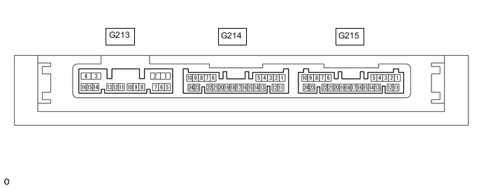
CHECK CERTIFICATION ECU (SMART KEY ECU ASSEMBLY) (w/ Entry and Start System)
-
Disconnect the G215 certification ECU (smart key ECU assembly) connector.
-
Measure the voltage and resistance according to the value(s) in the table below.
Tester Connection Wiring Color Terminal Description Condition Specified Condition G215-10 (+B) - Body ground V - Body ground Battery power supply Always 11 to 14 V G215-11 (E) - Body ground W-B - Body ground Ground Always Below 1 Ω -
Reconnect the G215 certification ECU (smart key ECU assembly) connector.
-
Measure the voltage and check for pulses according to the value(s) in the table below.
Tester Connection Wiring Color Terminal Description Condition Specified Condition G214-18 (RCO) - G215-11 (E) L - W-B Output to door control receiver
(Power supply for door control receiver. Certification ECU [smart key ECU assembly] outputs 5 V when receiver starts operating.)
-
Engine switch off
-
Electrical key transmitter sub-assembly brought outside detection area but kept inside wireless function operational area
-
Lock or unlock switch of electrical key transmitter sub-assembly not pressed → pressed
Proceed:
Pulse generation G214-19 (CSEL) - G215-11 (E) P - W-B Communication channel switching circuit
-
Engine switch off
-
All doors closed
Proceed:
Below 1 V → Pulse generation G214-20 (RDAM) - G215-11 (E) G - W-B Door control receiver verifies data received from electrical key transmitter sub-assembly.
Door control receiver sends data from electrical key transmitter sub-assembly to certification ECU (smart key ECU assembly) (Door control receiver intermittently grounds 12 V signal from certification ECU [smart key ECU assembly]).
-
Engine switch off
-
All doors locked
-
Electrical key transmitter sub-assembly not inside vehicle
-
Electrical key transmitter sub-assembly brought outside detection area but kept inside wireless function operational area
-
Lock or unlock switch of electrical key transmitter sub-assembly not pressed → pressed
Proceed:
Pulse generation -
-