SLIDING ROOF SYSTEM TERMINALS OF ECU
-
CHECK SLIDING ROOF DRIVE GEAR SUB-ASSEMBLY (SLIDING ROOF ECU)
-
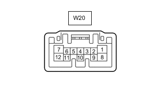
Disconnect the W20 sliding roof drive gear sub-assembly (sliding roof ECU) connector.
-
Measure the resistance and voltage according to the value(s) in the table below.
Tester Connection Wiring Color Terminal Description Condition Specified Condition W20-1 (IG) - Body ground L - Body ground IG power supply Ignition switch off Below 1 V Ignition switch ON 11 to 14 V W20-4 (UP) - Body ground R - Body ground Slide roof switch up signal Ignition switch ON, sliding roof tilted downward Tilt up switch on → off 1 kΩ or higher → Below 100 Ω W20-5 (CLS) - Body ground B - Body ground Slide roof switch close signal Ignition switch ON, sliding roof open Slide close switch on → off 1 kΩ or higher → Below 100 Ω W20-6 (DWN) - Body ground P - Body ground Slide roof switch down signal Ignition switch ON, sliding roof tilted upward Tilt down switch on → off 1 kΩ or higher → Below 100 Ω W20-7 (OPN) - Body ground LG - Body ground Slide roof switch open signal Ignition switch ON, sliding roof closed Slide open switch on → off 1 kΩ or higher → Below 100 Ω W20-8 (B) - Body ground W - Body ground Battery power supply Always 11 to 14 V W20-12 (E) - Body ground W-B - Body ground Ground Always Below 1 Ω
-
-
CHECK DRIVER SIDE JUNCTION BLOCK ASSEMBLY AND MAIN BODY ECU (MULTIPLEX NETWORK BODY ECU)
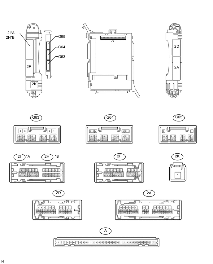
Text in Illustration *A for LHD *B for RHD
-
Remove the main body ECU (multiplex network body ECU) from the driver side junction block assembly Click here.
-
Measure the voltage and resistance according to the value(s) in the table below.
Tech Tips
Measure the values on the wire harness side with the connector disconnected.
Terminal No. (Symbol) Wiring Color Terminal Description Condition Specified Condition A-30 (BECU) - Body ground - Battery power supply Always 11 to 14 V A-31 (ALTB) - Body ground - Battery power supply Always 11 to 14 V A-32 (IG) - Body ground - Ignition switch power supply Ignition switch ON 11 to 14 V A-32 (IG) - Body ground - Ignition switch power supply Ignition switch off Below 1 V A-29 (ACC) - Body ground - ACC power supply Ignition switch ACC 11 to 14 V A-29 (ACC) - Body ground - ACC power supply Ignition switch off Below 1 V A-11 (GND1) - Body ground - Ground Always Below 1 Ω G63-3 (GND2) - Body ground W-B - Body ground Ground Always Below 1 Ω -
Install the main body ECU (multiplex network body ECU).
-
Measure the voltage according to the value(s) in the table below.
for LHD: Terminal No. (Symbol) Wiring Color Terminal Description Condition Specified Condition 2I-27 (FLCY) - Body ground R - Body ground Front door LH courtesy switch input Front door LH open Below 1 V 2I-27 (FLCY) - Body ground R - Body ground Front door LH courtesy switch input Front door LH closed 11 to 14 V G64-11 (L2) - Body ground GR - Body ground Driver side door key-linked lock input Driver side door key cylinder in lock position Below 1 V G64-11 (L2) - Body ground GR - Body ground Driver side door key-linked lock input Ignition switch off, all doors closed and driver side door key cylinder in neutral position Pulse generation (See waveform 1 or 2) G64-24 (UL3) - Body ground LG - Body ground Driver side door key-linked unlock input Driver side door key cylinder in unlock position Below 1 V G64-24 (UL3) - Body ground LG - Body ground Driver side door key-linked unlock input Ignition switch off, all doors closed and driver side door key cylinder in neutral position Pulse generation (See waveform 3 or 4) G64-26 (RDA) - Body ground* P - Body ground Door control receiver input No key in ignition key cylinder, all doors closed and transmitter switch off → on Pulse generation for RHD: Terminal No. (Symbol) Wiring Color Terminal Description Condition Specified Condition 2H-26 (FRCY) - Body ground B - Body ground Front door RH courtesy switch input Front door RH open Below 1 V 2H-26 (FRCY) - Body ground B - Body ground Front door RH courtesy switch input Front door RH closed 11 to 14 V G64-11 (L2) - Body ground GR - Body ground Driver side door key-linked lock input Driver side door key cylinder in lock position Below 1 V G64-11 (L2) - Body ground GR - Body ground Driver side door key-linked lock input Ignition switch off, all doors closed and driver side door key cylinder in neutral position Pulse generation (See waveform 1 or 2) G64-24 (UL3) - Body ground LG - Body ground Driver side door key-linked unlock input Driver side door key cylinder in unlock position Below 1 V G64-24 (UL3) - Body ground LG - Body ground Driver side door key-linked unlock input Ignition switch off, all doors closed and driver side door key cylinder in neutral position Pulse generation (See waveform 3 or 4) G64-26 (RDA) - Body ground* P - Body ground Door control receiver input No key in ignition key cylinder, all doors closed and transmitter switch off → on Pulse generation
-
*: w/o Entry and Start System
If the result is not as specified, the main body ECU (multiplex network body ECU) or driver side junction block assembly may have a malfunction.
-
-
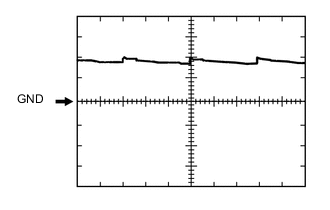
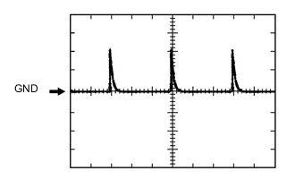
Using an oscilloscope, check waveform 1.
Waveform 1 (Reference) Item Content Terminal No. (Symbol) G64-11 (L2) - Body ground Tool Setting 5 V/DIV., 20 ms/DIV. Condition Ignition switch off, all doors closed and front door key cylinder in neutral position -
Using an oscilloscope, check waveform 2.
Waveform 2 (Reference) Item Content Terminal No. (Symbol) G64-11 (L2) - Body ground Tool Setting 5 V/DIV., 20 ms/DIV. Condition Ignition switch off, all doors closed and front door key cylinder in neutral position -
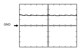
Using an oscilloscope, check waveform 3.
Waveform 3 (Reference) Item Content Terminal No. (Symbol) G64-24 (UL3) - Body ground Tool Setting 5 V/DIV., 20 ms/DIV. Condition Ignition switch off, all doors closed and driver side door key cylinder in neutral position -
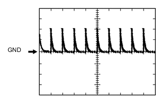
Using an oscilloscope, check waveform 4.
Waveform 4 (Reference) Item Content Terminal No. (Symbol) G64-24 (UL3) - Body ground Tool Setting 5 V/DIV., 20 ms/DIV. Condition Ignition switch off, all doors closed and driver side door key cylinder in neutral position
-
-
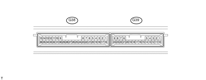
CHECK CERTIFICATION ECU (w/ Smart Key System)
-
Disconnect the G38 ECU connector.
-
Measure the voltage and resistance according to the value(s) in the table below.
Tech Tips
Measure the values on the wire harness side with the connector disconnected.
Terminal No. (Symbol) Wiring Color Terminal Description Condition Specified Condition G38-1 (+B) - G38-15 (E) V - W-B Battery power supply Always 11 to 14 V G38-15 (E) - Body ground W-B - Body ground Ground Always Below 1 Ω G38-16 (IG) - G38-15 (E) W - W-B IG power supply Ignition switch off Below 1 V G38-16 (IG) - G38-15 (E) W - W-B IG power supply Ignition switch ON 11 to 14 V G38-17 (CUTB) - G38-15 (E) L - W-B Battery power supply Always 11 to 14 V -
Reconnect the G38 ECU connector.
-
Measure the voltage according to the value(s) in the table below.
Terminal No. (Symbol) Wiring Color Terminal Description Condition Specified Condition G39-5 (RCO) - G38-15 (E) L - W-B Door control receiver power source Ignition switch off, all doors closed and transmitter switch not pressed Below 1 V G39-5 (RCO) - G38-15 (E) L - W-B Door control receiver power source Ignition switch off, all doors closed and transmitter switch pressed 4.5 to 5.5 V G39-15 (RDA) - G38-15 (E) G - W-B Door control receiver data input signal Ignition switch off 11 to 14 V pulse generation at regular intervals G39-16 (RSSI) - G38-15 (E) P - W-B Door control receiver electric wave existence signal All doors locked, all doors closed and transmitter switch not pressed 11 to 14 V G39-16 (RSSI) - G38-15 (E) P - W-B Door control receiver electric wave existence signal All doors locked, all doors closed and transmitter switch pressed Below 2 V
-