WINDSHIELD DEICER SWITCH INSPECTION
PROCEDURE
-
INSPECT OUTER MIRROR HEATER SWITCH ASSEMBLY
-
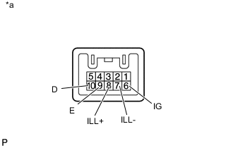
Text in Illustration *a Component without harness connected
(Outer Mirror Heater Switch Assembly)
Measure the resistance according to the value(s) in the table below.
Standard Resistance Tester Connection Switch Condition Specified Condition 6 (IG) - 9 (E) Outer mirror heater switch on Below 1 Ω 6 (IG) - 9 (E) Outer mirror heater switch off 10 kΩ or higher If the result is not as specified, replace the outer mirror heater switch assembly.
-
Apply battery voltage to the connector and check the LED illumination.
OK Measurement Condition Specified Condition Battery positive (+) → 6 (IG)
Battery negative (-) → 10 (D)
Indicator LED illuminates Battery positive (+) → 8 (ILL+)
Battery negative (-) → 7 (ILL-)
Illumination LED illuminates
-