SLIDING ROOF SYSTEM Sliding Roof ECU Power Source Circuit
DESCRIPTION
If the sliding function and tilt function do not operate, there may be a malfunction in the sliding roof drive gear sub-assembly power source circuit.
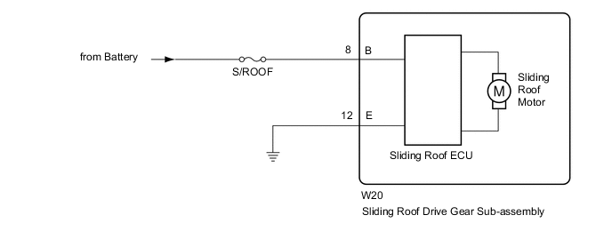
WIRING DIAGRAM
CAUTION / NOTICE / HINT
Note
-
When the sliding roof drive gear sub-assembly is removed and reinstalled or replaced, the sliding roof drive gear sub-assembly must be initialized Click here.
-
Inspect the fuses for circuits related to this system before performing the following inspection procedure.
PROCEDURE
-
READ VALUE USING GTS (ENGINE SWITCH SIGNAL)
-
Use the Data List to check if the ignition switch signal is functioning properly Click here.
Sliding Roof Tester Display Measurement Item/Range Normal Condition Diagnostic Note Ignition (Direct Signal) Ignition switch signal / ON or OFF ON: Ignition switch ON
OFF: Ignition switch off
- Ignition (MPX) Ignition switch signal (LIN signal) / ON or OFF ON: Ignition switch ON
OFF: Ignition switch off
- OK The intelligent tester displays as shown in the table according to the operation of each switch.
OK 
REPLACE SLIDING ROOF DRIVE GEAR SUB-ASSEMBLY Click here
NG 
-
-
CHECK HARNESS AND CONNECTOR (SLIDING ROOF ECU - BATTERY AND BODY GROUND)
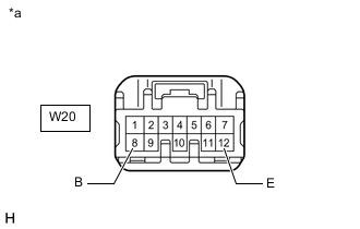
Text in Illustration *a Front view of wire harness connector
(to Sliding Roof Drive Gear Sub-assembly)
-
Disconnect the W20 ECU connector.
-
Measure the resistance and voltage according to the value(s) in the table below.
Standard Resistance Tester Connection Condition Specified Condition W20-12 (E) - Body ground Always Below 1 Ω Standard Voltage Tester Connection Condition Specified Condition W20-8 (B) - Body ground Always 11 to 14 V
OK
REPLACE SLIDING ROOF DRIVE GEAR SUB-ASSEMBLY Click here
NG
REPAIR OR REPLACE HARNESS OR CONNECTOR
-