SLIDING ROOF SYSTEM Sliding Roof Control Switch Circuit
DESCRIPTION
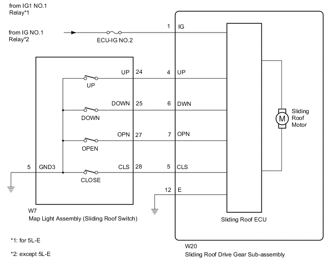
The sliding roof drive gear sub-assembly (sliding roof ECU) receives each signal when the map light assembly (slide roof switch) is operated and drives its built-in motor.
WIRING DIAGRAM
CAUTION / NOTICE / HINT
Note
When the sliding roof drive gear sub-assembly is removed and reinstalled or replaced, the sliding roof drive gear sub-assembly must be initialized Click here.
PROCEDURE
-
PERFORM ACTIVE TEST USING GTS (SLIDING ROOF)
-
Select the Active Test, use the GTS to generate a control command, and then check that the sliding roof slides open/closed and tilts up/down Click here.
Sliding Roof Tester Display Test Part Control Range Diagnostic Note Slide Roof Operate sliding roof Opn/Dwn: Sliding roof slide open or tilt down operation occurs
Clos/Up: Sliding roof slide close or tilt up operation occurs
OFF: Sliding roof not operating
- OK The sliding roof operates normally.
OK 
REPLACE SLIDING ROOF DRIVE GEAR SUB-ASSEMBLY Click here
NG 
-
-
READ VALUE USING GTS (SLIDING ROOF)
-
Using the GTS, read the Data List Click here.
Sliding Roof Tester Display Measurement Item/Range Normal Condition Diagnostic Note Open Switch Slide open switch signal / ON or OFF ON: Slide open switch pressed
OFF: Slide open switch not pressed
- Close Switch Slide close switch signal / ON or OFF ON: Slide close switch pressed
OFF: Slide close switch not pressed
- Up Switch Tilt up switch signal / ON or OFF ON: Tilt up switch pressed
OFF: Tilt up switch not pressed
- Down Switch Tilt down switch signal / ON or OFF ON: Tilt down switch pressed
OFF: Tilt down switch not pressed
- OK The GTS display changes according to switch operation as shown in the table.
OK
REPLACE SLIDING ROOF DRIVE GEAR SUB-ASSEMBLY Click here
NG
-
-
INSPECT MAP LIGHT ASSEMBLY
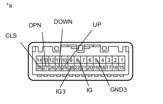
Text in Illustration *a Component without harness connected
(Map Light Assembly)
-
Remove the map light assembly Click here.
-
Measure the resistance according to the value(s) in the table below.
Standard Resistance Tester Connection Switch Condition Specified Condition 8 (IG) - 23 (IG3) Always Below 1 Ω 24 (UP) - 5 (GND3) Tilt up switch pressed Below 1 Ω 24 (UP) - 5 (GND3) Tilt up switch not pressed 10 kΩ or higher 25 (DOWN) - 5 (GND3) Tilt down switch pressed Below 1 Ω 25 (DOWN) - 5 (GND3) Tilt down switch not pressed 10 kΩ or higher 27 (OPN) - 5 (GND3) Slide open switch pressed Below 1 Ω 27 (OPN) - 5 (GND3) Slide open switch not pressed 10 kΩ or higher 28 (CLS) - 5 (GND3) Slide close switch pressed Below 1 Ω 28 (CLS) - 5 (GND3) Slide close switch not pressed 10 kΩ or higher
NG
REPLACE MAP LIGHT ASSEMBLY Click here
OK
-
-
CHECK HARNESS AND CONNECTOR (SLIDING ROOF ECU - BATTERY AND BODY GROUND)
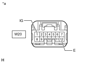
Text in Illustration *a Front view of wire harness connector
(to Sliding Roof Drive Gear Sub-assembly)
-
Disconnect the W20 ECU connector.
-
Measure the resistance and voltage according to the value(s) in the table below.
Standard Resistance Tester Connection Condition Specified Condition W20-12 (E) - Body ground Always Below 1 Ω Standard Voltage Tester Connection Switch Condition Specified Condition W20-1 (IG) - Body ground Ignition switch ON 11 to 14 V W20-1 (IG) - Body ground Ignition switch off Below 1 V
NG
REPAIR OR REPLACE HARNESS OR CONNECTOR
OK
-
-
CHECK HARNESS AND CONNECTOR (SLIDING ROOF ECU - MAP LIGHT ASSEMBLY AND BODY GROUND)
-
Disconnect the W20 ECU connector.
-
Disconnect the W7 switch connector.
-
Measure the resistance according to the value(s) in the table below.
Standard Resistance Tester Connection Condition Specified Condition W20-4 (UP) - W7-24 (UP) Always Below 1 Ω W20-5 (CLS) - W7-28 (CLS) Always Below 1 Ω W20-6 (DWN) - W7-25 (DOWN) Always Below 1 Ω W20-7 (OPN) - W7-27 (OPN) Always Below 1 Ω W7-5 (GND3) - Body ground Always Below 1 Ω W20-12 (E) - Body ground Always Below 1 Ω W20-4 (UP) or W7-24 (UP) - Body ground Always 10 kΩ or higher W20-5 (CLS) or W7-28 (CLS) - Body ground Always 10 kΩ or higher W20-6 (DWN) or W7-25 (DOWN) - Body ground Always 10 kΩ or higher W20-7 (OPN) or W7-27 (OPN) - Body ground Always 10 kΩ or higher
OK
REPLACE SLIDING ROOF DRIVE GEAR SUB-ASSEMBLY Click here
NG
REPAIR OR REPLACE HARNESS OR CONNECTOR
-