WINDSHIELD DEICER SYSTEM TERMINALS OF ECU
-
CHECK AIR CONDITIONING AMPLIFIER ASSEMBLY
-
Disconnect the G25 air conditioning amplifier assembly connector.
-
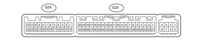
Measure the voltage and resistance according to the value(s) in the table below.
Terminal No. (Symbol) Wiring Color Terminal Description Condition Specified Condition G25-21 (B) - G25-14 (GND) V - W-B Battery power source Always 11 to 14 V G25-1 (IG+) - G25-14 (GND) L - W-B Ignition power supply Ignition switch ON 11 to 14 V G25-1 (IG+) - G25-14 (GND) L - W-B Ignition power supply Ignition switch off Below 1 V G25-14 (GND) - Body ground W-B - Body ground Ground Always Below 1 Ω -
Reconnect the G25 air conditioning amplifier assembly connector.
-
Measure the voltage according to the value(s) in the table below.
Terminal No. (Symbol) Wiring Color Terminal Description Condition Specified Condition G25-40 (FDEF) - Body ground G - Body ground Front wiper deicer relay (DEICER) operation signal Ignition switch ON, front wiper deicer switch off 11 to 14 V G25-40 (FDEF) - Body ground G - Body ground Front wiper deicer relay (DEICER) operation signal Ignition switch ON, front wiper deicer switch on Below 1 V G24-11 (FDFI) - Body ground B - Body ground Front wiper deicer switch indicator signal output Ignition switch ON, front wiper deicer switch off 11 to 14 V G24-11 (FDFI) - Body ground B - Body ground Front wiper deicer switch indicator signal output Ignition switch ON, front wiper deicer switch on Below 1 V G24-5 (SW 1) - Body ground R - Body ground Front wiper deicer switch signal input Ignition switch ON, front wiper deicer switch off Below 1 V G24-5 (SW 1) - Body ground R - Body ground Front wiper deicer switch signal input Ignition switch ON, front wiper deicer switch on 11 to 14 V
-