WINDSHIELD DEICER SYSTEM Windshield Deicer does not Operate
DESCRIPTION
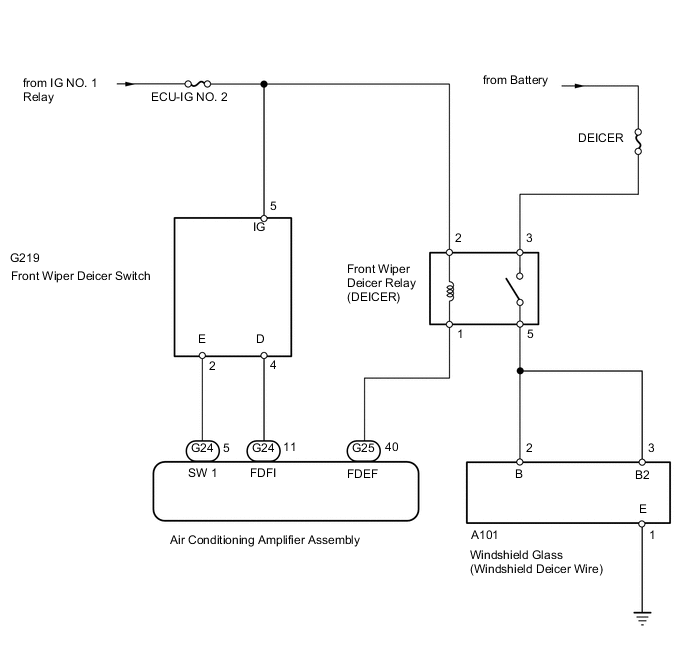
When the front wiper deicer switch is turned on, the front wiper deicer switch operation information is sent to the air conditioning amplifier assembly. When the air conditioning amplifier assembly receives the front wiper deicer switch operation information, it turns the front wiper deicer relay (DEICER) on and operates the windshield deicer system.
WIRING DIAGRAM
CAUTION / NOTICE / HINT
Note
-
Inspect the fuses for circuits related to this system before performing the following procedure.
-
Troubleshoot the windshield deicer system after confirming that the air conditioning system is functioning properly.
PROCEDURE
-
PERFORM ACTIVE TEST USING GTS (DEICER RELAY (FRONT))
-
Using the GTS, perform the Active Test.
Air Conditioner Tester Display Measurement Item Control Range Diagnostic Note Deicer Relay (Front) Windshield glass (windshield deicer wire) OFF or ON - OK The windshield deicer system operates normally. Result Proceed to OK NG
NG 
CHECK HARNESS AND CONNECTOR (WINDSHIELD GLASS [WINDSHIELD DEICER WIRE] - BATTERY) Click here
OK 
-
-
INSPECT FRONT WIPER DEICER SWITCH
-
Remove the front wiper deicer switch.
-
Inspect the front wiper deicer switch.
Result Proceed to OK NG
NG 
REPLACE FRONT WIPER DEICER SWITCH Click here
OK
-
-
CHECK HARNESS AND CONNECTOR (FRONT WIPER DEICER SWITCH - AIR CONDITIONING AMPLIFIER ASSEMBLY)
-
Disconnect the G219 front wiper deicer switch connector.
-
Disconnect the G24 air conditioning amplifier assembly connector.
-
Measure the resistance according to the value(s) in the table below.
Standard Resistance Tester Connection Condition Specified Condition G219-2 (E) - G24-5 (SW 1) Always Below 1 Ω G219-4 (D) - G24-11 (FDFI) Always Below 1 Ω G219-2 (E) or G24-5 (SW 1) - Body ground Always 10 kΩ or higher G219-4 (D) or G24-11 (FDFI) - Body ground Always 10 kΩ or higher Result Proceed to OK NG
OK
REPLACE AIR CONDITIONING AMPLIFIER ASSEMBLY Click here
NG
REPAIR OR REPLACE HARNESS OR CONNECTOR
-
-
CHECK HARNESS AND CONNECTOR (WINDSHIELD GLASS [WINDSHIELD DEICER WIRE] - BATTERY)
-
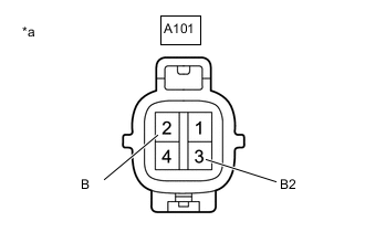
*a Front view of wire harness connector
(to Windshield Glass [Windshield Deicer Wire])
Disconnect the windshield glass (windshield deicer wire) connector.
-
Measure the voltage according to the value(s) in the table below.
Standard Voltage Tester Connection Switch Condition Specified Condition A101-2 (B) - Body ground Ignition switch ON, front wiper deicer switch off Below 1 V Ignition switch ON, front wiper deicer switch on 11 to 14 V A101-3 (B2) - Body ground Ignition switch ON, front wiper deicer switch off Below 1 V Ignition switch ON, front wiper deicer switch on 11 to 14 V Result Proceed to OK NG
NG
INSPECT FRONT WIPER DEICER RELAY (DEICER) Click here
OK
-
-
CHECK HARNESS AND CONNECTOR (WINDSHIELD GLASS [WINDSHIELD DEICER WIRE] - BODY GROUND)
-
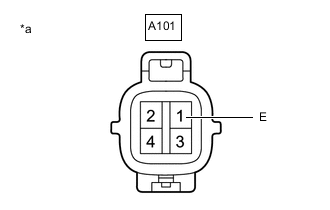
*a Front view of wire harness connector
(to Windshield Glass [Windshield Deicer Wire])
Disconnect the windshield glass (windshield deicer wire) connector.
-
Measure the resistance according to the value(s) in the table below.
Standard Resistance Tester Connection Condition Specified Condition A101-1 (E) - Body ground Always Below 1 Ω Result Proceed to OK NG
OK
REPLACE WINDSHIELD GLASS (WINDSHIELD DEICER WIRE) Click here
NG
REPAIR OR REPLACE HARNESS OR CONNECTOR
-
-
INSPECT FRONT WIPER DEICER RELAY (DEICER)
-
Remove the front wiper deicer relay (DEICER) from the No. 5 engine room relay block.
-
Inspect the front wiper deicer relay (DEICER).
Result Proceed to OK NG
NG
REPLACE FRONT WIPER DEICER RELAY (DEICER)
OK
-
-
CHECK HARNESS AND CONNECTOR (FRONT WIPER DEICER RELAY [DEICER] - BATTERY)
-
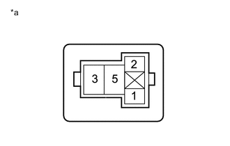
*a Front view of wire harness connector
(to Front Wiper Deicer Relay [DEICER])
Remove the front wiper deicer relay (DEICER) from the No. 5 engine room relay block.
-
Measure the voltage according to the value(s) in the table below.
Standard Voltage Tester Connection Switch Condition Specified Condition Front wiper deicer relay (DEICER) terminal 3 - Body ground Always 11 to 14 V Front wiper deicer relay (DEICER) terminal 2 - Body ground Ignition switch ON 11 to 14 V Result Proceed to OK NG
NG
REPAIR OR REPLACE HARNESS OR CONNECTOR
OK
-
-
CHECK HARNESS AND CONNECTOR (FRONT WIPER DEICER RELAY [DEICER] - AIR CONDITIONING AMPLIFIER ASSEMBLY AND WINDSHIELD GLASS [WINDSHIELD DEICER WIRE])
-
Remove the front wiper deicer relay (DEICER) from the No. 5 engine room relay block.
-
Disconnect the A101 windshield glass (windshield deicer wire) connector.
-
Disconnect the G25 air conditioning amplifier assembly connector.
-
Measure the resistance according to the value(s) in the table below.
Standard Resistance Tester Connection Condition Specified Condition Front wiper deicer relay (DEICER) terminal 5 - A101-2 (B) Always Below 1 Ω Front wiper deicer relay (DEICER) terminal 5 - A101-3 (B2) Always Below 1 Ω Front wiper deicer relay (DEICER) terminal 1 - G25-40 (FDEF) Always Below 1 Ω Front wiper deicer relay (DEICER) terminal 5 or A101-2 (B) - Body ground Always 10 kΩ or higher Front wiper deicer relay (DEICER) terminal 5 or A101-3 (B2) - Body ground Always 10 kΩ or higher Front wiper deicer relay (DEICER) terminal 1 or G25-40 (FDEF) - Body ground Always 10 kΩ or higher Result Proceed to OK NG
OK
REPLACE AIR CONDITIONING AMPLIFIER ASSEMBLY Click here
NG
REPAIR OR REPLACE HARNESS OR CONNECTOR
-