POWER WINDOW CONTROL SYSTEM TERMINALS OF ECU
-
CHECK MULTIPLEX NETWORK MASTER SWITCH ASSEMBLY

Text in Illustration *A for LHD *B for RHD
-
*1: for LHD
-
*2: for RHD
-
Disconnect the K4*1 or J9*2 multiplex network master switch connector.
-
Measure the voltage and resistance according to the value(s) in the table below.
Tech Tips
Measure the values on the wire harness side with the connector disconnected.
for LHD: Terminal No. (Symbol) Wiring Color Terminal Description Condition Specified Condition K4-11 (B) - K4-12 (GND) L - W-B Power supply Always 11 to 14 V K4-12 (GND) - Body ground W-B - Body ground Ground Always Below 1 Ω for RHD: Terminal No. (Symbol) Wiring Color Terminal Description Condition Specified Condition J9-11 (B) - J9-12 (GND) L - W-B Power supply Always 11 to 14 V J9-12 (GND) - Body ground W-B - Body ground Ground Always Below 1 Ω -
Reconnect the K4*1 or J9*2 multiplex network master switch connector.
-
Measure the voltage according to the value(s) in the table below.
for LHD: Terminal No. (Symbol) Wiring Color Terminal Description Condition Specified Condition K4-15 (DOWN) - K4-12 (GND) LA-B - W-B Power window motor down input Ignition switch ON, driver side power window regulator switch off 11 to 14 V K4-15 (DOWN) - K4-12 (GND) LA-B - W-B Power window motor down input Ignition switch ON, driver side power window switch down (Manual operation) Below 1 V K4-18 (LED) - K4-12 (GND) LA-V - W-B LED illumination signal Ignition switch ON 11 to 14 V K4-18 (LED) - K4-12 (GND) LA-V - W-B LED illumination signal Ignition switch off Below 1 V K4-20 (UP) - K4-12 (GND) LA-P - W-B Power window motor up input Ignition switch ON, driver side power window switch off 11 to 14 V K4-20 (UP) - K4-12 (GND) LA-P - W-B Power window motor up input Ignition switch ON, driver side power window switch up (Manual operation) Below 1 V for RHD: Terminal No. (Symbol) Wiring Color Terminal Description Condition Specified Condition J9-15 (DOWN) - J9-12 (GND) LA-B - W-B Power window motor down input Ignition switch ON, driver side power window regulator switch off 11 to 14 V J9-15 (DOWN) - J9-12 (GND) LA-B - W-B Power window motor down input Ignition switch ON, driver side power window switch down (Manual operation) Below 1 V J9-18 (LED) - J9-12 (GND) LA-V - W-B LED illumination signal Ignition switch ON 11 to 14 V J9-18 (LED) - J9-12 (GND) LA-V - W-B LED illumination signal Ignition switch off Below 1 V J9-20 (UP) - J9-12 (GND) LA-P - W-B Power window motor up input Ignition switch ON, driver side power window switch off 11 to 14 V J9-20 (UP) - J9-12 (GND) LA-P - W-B Power window motor up input Ignition switch ON, driver side power window switch up (Manual operation) Below 1 V
-
-
CHECK POWER WINDOW REGULATOR SWITCH ASSEMBLY

Text in Illustration *A for LHD *B for RHD
-
*1: for LHD
-
*2: for RHD
-
Disconnect the J1*1 or K10*2 power window regulator switch connector.
-
Measure the resistance according to the value(s) in the table below.
Tech Tips
Measure the values on the wire harness side with the connector disconnected.
for LHD: Terminal No. (Symbol) Wiring Color Terminal Description Condition Specified Condition J1-1 (GND) - Body ground W-B - Body ground Ground Always Below 1 Ω for RHD: Terminal No. (Symbol) Wiring Color Terminal Description Condition Specified Condition K10-1 (GND) - Body ground W-B - Body ground Ground Always Below 1 Ω -
Reconnect the J1*1 or K10*2 power window regulator switch connector.
-
Measure the voltage according to the value(s) in the table below.
for LHD: Terminal No. (Symbol) Wiring Color Terminal Description Condition Specified Condition J1-6 (UP) - J1-1 (GND) L - W-B Power window motor up input Ignition switch ON, power window regulator switch off 11 to 14 V J1-6 (UP) - J1-1 (GND) L - W-B Power window motor up input Ignition switch ON, power window regulator switch up Below 1 V J1-8 (AUTO) - J1-1 (GND) P - W-B Power window motor auto up or down input Ignition switch ON, door glass fully open 11 to 14 V J1-8 (AUTO) - J1-1 (GND) P - W-B Power window motor auto up or down input Ignition switch ON, power window auto up or down function operating Below 1 V J1-8 (AUTO) - J1-1 (GND) P - W-B Power window motor auto up or down input Ignition switch ON, door glass fully closed 11 to 14 V J1-4 (LED) - J1-1 (GND) V - W-B LED illumination signal Ignition switch ON 11 to 14 V J1-4 (LED) - J1-1 (GND) V - W-B LED illumination signal Ignition switch off Below 1 V J1-7 (DOWN) - J1-1 (GND) B - W-B Power window motor down input Ignition switch ON, power window regulator switch off 11 to 14 V J1-7 (DOWN) - J1-1 (GND) B - W-B Power window motor down input Ignition switch ON, power window regulator switch down Below 1 V for RHD: Terminal No. (Symbol) Wiring Color Terminal Description Condition Specified Condition K10-6 (UP) - K10-1 (GND) L - W-B Power window motor up input Ignition switch ON, power window regulator switch off 11 to 14 V K10-6 (UP) - K10-1 (GND) L - W-B Power window motor up input Ignition switch ON, power window regulator switch up Below 1 V K10-8 (AUTO) - K10-1 (GND) P - W-B Power window motor auto up or down input Ignition switch ON, door glass fully open 11 to 14 V K10-8 (AUTO) - K10-1 (GND) P - W-B Power window motor auto up or down input Ignition switch ON, power window auto up or down function operating Below 1 V K10-8 (AUTO) - K10-1 (GND) P - W-B Power window motor auto up or down input Ignition switch ON, door glass fully closed 11 to 14 V K10-4 (LED) - K10-1 (GND) V - W-B LED illumination signal Ignition switch ON 11 to 14 V K10-4 (LED) - K10-1 (GND) V - W-B LED illumination signal Ignition switch off Below 1 V K10-7 (DOWN) - K10-1 (GND) B - W-B Power window motor down input Ignition switch ON, power window regulator switch off 11 to 14 V K10-7 (DOWN) - K10-1 (GND) B - W-B Power window motor down input Ignition switch ON, power window regulator switch down Below 1 V
-
-
CHECK REAR POWER WINDOW REGULATOR SWITCH ASSEMBLY LH (for 5 Door)

-
Disconnect the M2 rear power window regulator switch connector.
-
Measure the resistance according to the value(s) in the table below.
Tech Tips
Measure the values on the wire harness side with the connector disconnected.
Terminal No. (Symbol) Wiring Color Terminal Description Condition Specified Condition M2-1 (GND) - Body ground W-B - Body ground Ground Always Below 1 Ω -
Reconnect the M2 rear power window regulator switch connector.
-
Measure the voltage according to the value(s) in the table below.
Terminal No. (Symbol) Wiring Color Terminal Description Condition Specified Condition M2-6 (UP) - M2-1 (GND) L - W-B Power window motor up input Ignition switch ON, power window regulator switch off 11 to 14 V M2-6 (UP) - M2-1 (GND) L - W-B Power window motor up input Ignition switch ON, power window regulator switch up Below 1 V M2-8 (AUTO) - M2-1 (GND) P - W-B Power window motor auto up or down input Ignition switch ON, door glass fully open 11 to 14 V M2-8 (AUTO) - M2-1 (GND) P - W-B Power window motor auto up or down input Ignition switch ON, power window auto up or down function operating Below 1 V M2-8 (AUTO) - M2-1 (GND) P - W-B Power window motor auto up or down input Ignition switch ON, door glass fully closed 11 to 14 V M2-4 (LED) - M2-1 (GND) V - W-B LED illumination signal Ignition switch ON 11 to 14 V M2-4 (LED) - M2-1 (GND) V - W-B LED illumination signal Ignition switch off Below 1 V M2-7 (DOWN) - M2-1 (GND) B - W-B Power window motor down input Ignition switch ON, power window regulator switch off 11 to 14 V M2-7 (DOWN) - M2-1 (GND) B - W-B Power window motor down input Ignition switch ON, power window regulator switch down Below 1 V
-
-
CHECK REAR POWER WINDOW REGULATOR SWITCH ASSEMBLY RH (for 5 Door)

-
Disconnect the L2 rear power window regulator switch connector.
-
Measure the resistance according to the value(s) in the table below.
Tech Tips
Measure the values on the wire harness side with the connector disconnected.
Terminal No. (Symbol) Wiring Color Terminal Description Condition Specified Condition L2-1 (GND) - Body ground W-B - Body ground Ground Always Below 1 Ω -
Reconnect the L2 rear power window regulator switch connector.
-
Measure the voltage according to the value(s) in the table below.
Terminal No. (Symbol) Wiring Color Terminal Description Condition Specified Condition L2-6 (UP) - L2-1 (GND) L - W-B Power window motor up input Ignition switch ON, power window regulator switch off 11 to 14 V L2-6 (UP) - L2-1 (GND) L - W-B Power window motor up input Ignition switch ON, power window regulator switch up Below 1 V L2-8 (AUTO) - L2-1 (GND) P - W-B Power window motor auto up or down input Ignition switch ON, door glass fully open 11 to 14 V L2-8 (AUTO) - L2-1 (GND) P - W-B Power window motor auto up or down input Ignition switch ON, power window auto up or down function operating Below 1 V L2-8 (AUTO) - L2-1 (GND) P - W-B Power window motor auto up or down input Ignition switch ON, door glass fully closed 11 to 14 V L2-4 (LED) - L2-1 (GND) V - W-B LED illumination signal Ignition switch ON 11 to 14 V L2-4 (LED) - L2-1 (GND) V - W-B LED illumination signal Ignition switch off Below 1 V L2-7 (DOWN) - L2-1 (GND) B - W-B Power window motor down input Ignition switch ON, power window regulator switch off 11 to 14 V L2-7 (DOWN) - L2-1 (GND) B - W-B Power window motor down input Ignition switch ON, power window regulator switch down Below 1 V
-
-
CHECK FRONT POWER WINDOW REGULATOR MOTOR ASSEMBLY LH

-
*1: for LHD
-
*2: for RHD
-
Disconnect the K7 power window regulator motor connector.
-
Measure the voltage and resistance according to the value(s) in the table below.
Tech Tips
Measure the values on the wire harness side with the connector disconnected.
Terminal No. (Symbol) Wiring Color Terminal Description Condition Specified Condition K7-1 (GND) - Body ground W-B - Body ground Ground Always Below 1 Ω K7-2 (B) - Body ground R - Body ground*1
G - Body ground*2
Battery power supply Always 11 to 14 V -
Reconnect the K7 power window regulator motor connector.
-
Measure the voltage according to the value(s) in the table below.
Terminal No. (Symbol) Wiring Color Terminal Description Condition Specified Condition K7-5 (LED) - K7-1 (GND) LA-V - W-B*1
V - W-B*2
LED illumination signal Ignition switch ON 11 to 14 V K7-5 (LED) - K7-1 (GND) LA-V - W-B*1
V - W-B*2
LED illumination signal Ignition switch off Below 1 V K7-7 (DOWN) - K7-1 (GND) LA-B - W-B*1
B - W-B*2
Power window motor down output Ignition switch ON, power window regulator master switch off 11 to 14 V K7-7 (DOWN) - K7-1 (GND) LA-B - W-B*1
B - W-B*2
Power window motor down output Ignition switch ON, power window regulator master switch down Below 1 V K7-7 (DOWN) - K7-1 (GND) LA-B - W-B*1
B - W-B*2
Power window motor down output Ignition switch ON, door glass fully closed 11 to 14 V K7-7 (DOWN) - K7-1 (GND) LA-B - W-B*1
B - W-B*2
Power window motor down output Ignition switch ON, power window auto down function operating Below 1 V K7-7 (DOWN) - K7-1 (GND) LA-B - W-B*1
B - W-B*2
Power window motor down output Ignition switch ON, door glass fully open 11 to 14 V K7-10 (UP) - K7-1 (GND) LA-P - W-B*1
L - W-B*2
Power window motor up output Ignition switch ON, power window regulator master switch off 11 to 14 V K7-10 (UP) - K7-1 (GND) LA-P - W-B*1
L - W-B*2
Power window motor up output Ignition switch ON, power window regulator master switch up Below 1 V K7-10 (UP) - K7-1 (GND) LA-P - W-B*1
L - W-B*2
Power window motor up output Ignition switch ON, door glass fully open 11 to 14 V K7-10 (UP) - K7-1 (GND) LA-P - W-B*1
L - W-B*2
Power window motor up output Ignition switch ON, power window auto up function operating Below 1 V K7-10 (UP) - K7-1 (GND) LA-P - W-B*1
L - W-B*2
Power window motor up output Ignition switch ON, door glass fully closed 11 to 14 V
-
-
CHECK FRONT POWER WINDOW REGULATOR MOTOR ASSEMBLY RH

-
*1: for LHD
-
*2: for RHD
-
Disconnect the J7 power window regulator motor connector.
-
Measure the voltage and resistance according to the value(s) in the table below.
Tech Tips
Measure the values on the wire harness side with the connector disconnected.
Terminal No. (Symbol) Wiring Color Terminal Description Condition Specified Condition J7-1 (GND) - Body ground W-B - Body ground Ground Always Below 1 Ω J7-2 (B) - Body ground G - Body ground*1
R - Body ground*2
Battery power supply Always 11 to 14 V -
Reconnect the J7 power window regulator motor connector.
-
Measure the voltage according to the value(s) in the table below.
Terminal No. (Symbol) Wiring Color Terminal Description Condition Specified Condition J7-5 (LED) - J7-1 (GND) V - W-B*1
LA-V - W-B*2
LED illumination signal Ignition switch ON 11 to 14 V J7-5 (LED) - J7-1 (GND) V - W-B*1
LA-V - W-B*2
LED illumination signal Ignition switch off Below 1 V J7-7 (DOWN) - J7-1 (GND) B - W-B*1
LA-B - W-B*2
Power window motor down output Ignition switch ON, power window regulator switch off 11 to 14 V J7-7 (DOWN) - J7-1 (GND) B - W-B*1
LA-B - W-B*2
Power window motor down output Ignition switch ON, power window regulator switch down Below 1 V J7-7 (DOWN) - J7-1 (GND) B - W-B*1
LA-B - W-B*2
Power window motor down output Ignition switch ON, door glass fully closed 11 to 14 V J7-7 (DOWN) - J7-1 (GND) B - W-B*1
LA-B - W-B*2
Power window motor down output Ignition switch ON, power window auto down function operating Below 1 V J7-7 (DOWN) - J7-1 (GND) B - W-B*1
LA-B - W-B*2
Power window motor down output Ignition switch ON, door glass fully open 11 to 14 V J7-10 (UP) - J7-1 (GND) L - W-B*1
LA-P - W-B*2
Power window motor up output Ignition switch ON, power window regulator switch off 11 to 14 V J7-10 (UP) - J7-1 (GND) L - W-B*1
LA-P - W-B*2
Power window motor up output Ignition switch ON, power window regulator switch up Below 1 V J7-10 (UP) - J7-1 (GND) L - W-B*1
LA-P - W-B*2
Power window motor up output Ignition switch ON, door glass fully open 11 to 14 V J7-10 (UP) - J7-1 (GND) L - W-B*1
LA-P - W-B*2
Power window motor up output Ignition switch ON, power window auto up function operating Below 1 V J7-10 (UP) - J7-1 (GND) L - W-B*1
LA-P - W-B*2
Power window motor up output Ignition switch ON, door glass fully closed 11 to 14 V
-
-
CHECK REAR POWER WINDOW REGULATOR MOTOR ASSEMBLY LH (for 5 Door)

-
Disconnect the M4 rear power window regulator motor connector.
-
Measure the voltage and resistance according to the value(s) in the table below.
Tech Tips
Measure the values on the wire harness side with the connector disconnected.
Terminal No. (Symbol) Wiring Color Terminal Description Condition Specified Condition M4-1 (GND) - Body ground W-B - Body ground Ground Always Below 1 Ω M4-2 (B) - Body ground W - Body ground Battery power supply Always 11 to 14 V -
Reconnect the M4 rear power window regulator motor connector.
-
Measure the voltage according to the value(s) in the table below.
Terminal No. (Symbol) Wiring Color Terminal Description Condition Specified Condition M4-5 (LED) - M4-1 (GND) V - W-B LED illumination signal Ignition switch ON 11 to 14 V M4-5 (LED) - M4-1 (GND) V - W-B LED illumination signal Ignition switch off Below 1 V M4-7 (DOWN) - M4-1 (GND) B - W-B Power window motor down input Ignition switch ON, power window regulator switch off 11 to 14 V M4-7 (DOWN) - M4-1 (GND) B - W-B Power window motor down input Ignition switch ON, power window regulator switch down Below 1 V M4-7 (DOWN) - M4-1 (GND) B - W-B Power window motor down input Ignition switch ON, door glass fully closed 11 to 14 V M4-7 (DOWN) - M4-1 (GND) B - W-B Power window motor down input Ignition switch ON, power window auto down function operating Below 1 V M4-7 (DOWN) - M4-1 (GND) B - W-B Power window motor down input Ignition switch ON, door glass fully open 11 to 14 V M4-10 (UP) - M4-1 (GND) L - W-B Power window motor up output Ignition switch ON, power window regulator switch off 11 to 14 V M4-10 (UP) - M4-1 (GND) L - W-B Power window motor up output Ignition switch ON, power window regulator switch up Below 1 V M4-10 (UP) - M4-1 (GND) L - W-B Power window motor up output Ignition switch ON, door glass fully open 11 to 14 V M4-10 (UP) - M4-1 (GND) L - W-B Power window motor up output Ignition switch ON, power window auto up function operating Below 1 V M4-10 (UP) - M4-1 (GND) L - W-B Power window motor up output Ignition switch ON, door glass fully closed 11 to 14 V
-
-
CHECK REAR POWER WINDOW REGULATOR MOTOR ASSEMBLY RH (for 5 Door)

-
Disconnect the L4 rear window regulator motor connector.
-
Measure the voltage and resistance according to the value(s) in the table below.
Tech Tips
Measure the values on the wire harness side with the connector disconnected.
Terminal No. (Symbol) Wiring Color Terminal Description Condition Specified Condition L4-1 (GND) - Body ground W-B - Body ground Ground Always Below 1 Ω L4-2 (B) - Body ground W - Body ground Battery power supply Always 11 to 14 V -
Reconnect the L4 rear power window regulator motor connector.
-
Measure the voltage according to the value(s) in the table below.
Terminal No. (Symbol) Wiring Color Terminal Description Condition Specified Condition L4-5 (LED) - L4-1 (GND) V - W-B LED illumination signal Ignition switch ON 11 to 14 V L4-5 (LED) - L4-1 (GND) V - W-B LED illumination signal Ignition switch off Below 1 V L4-7 (DOWN) - L4-1 (GND) B - W-B Power window motor down output Ignition switch ON, power window regulator switch off 11 to 14 V L4-7 (DOWN) - L4-1 (GND) B - W-B Power window motor down output Ignition switch ON, power window regulator switch down Below 1 V L4-7 (DOWN) - L4-1 (GND) B - W-B Power window motor down output Ignition switch ON, door glass fully closed 11 to 14 V L4-7 (DOWN) - L4-1 (GND) B - W-B Power window motor down output Ignition switch ON, power window auto down function operating Below 1 V L4-7 (DOWN) - L4-1 (GND) B - W-B Power window motor down output Ignition switch ON, door glass fully open 11 to 14 V L4-10 (UP) - L4-1 (GND) L - W-B Power window motor up output Ignition switch ON, power window regulator switch off 11 to 14 V L4-10 (UP) - L4-1 (GND) L - W-B Power window motor up output Ignition switch ON, power window regulator switch up Below 1 V L4-10 (UP) - L4-1 (GND) L - W-B Power window motor up output Ignition switch ON, door glass fully open 11 to 14 V L4-10 (UP) - L4-1 (GND) L - W-B Power window motor up output Ignition switch ON, power window auto up function operating Below 1 V L4-10 (UP) - L4-1 (GND) L - W-B Power window motor up output Ignition switch ON, door glass fully closed 11 to 14 V
-
-
CHECK DRIVER SIDE JUNCTION BLOCK ASSEMBLY AND MAIN BODY ECU (MULTIPLEX NETWORK BODY ECU) (for 5L-E)
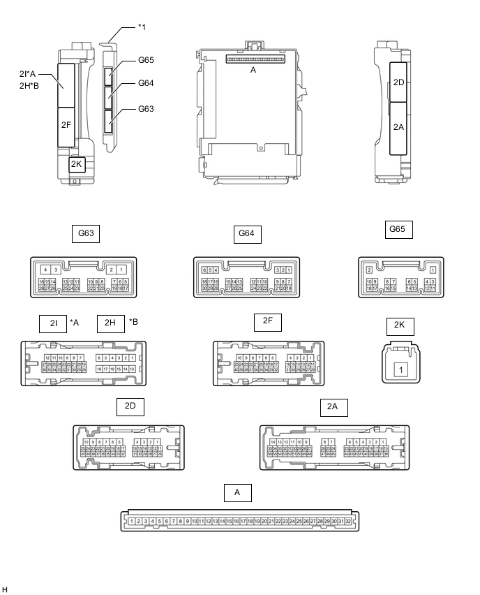
*A for LHD *B for RHD *1 Main Body ECU (Multiplex Network Body ECU) - -
-
Remove the main body ECU (multiplex network body ECU).
-
Measure the voltage and resistance according to the value(s) in the table below.
Terminal No. (Symbol) Wiring Color Terminal Description Condition Specified Condition A-30 (BECU) - Body ground - Battery power supply Always 11 to 14 V A-31 (ALTB) - Body ground - Battery power supply Always 11 to 14 V A-32 (IG) - Body ground - Ignition switch power supply Ignition switch ON 11 to 14 V A-32 (IG) - Body ground - Ignition switch power supply Ignition switch off Below 1 V A-29 (ACC) - Body ground - ACC power supply Ignition switch ACC 11 to 14 V A-29 (ACC) - Body ground - ACC power supply Ignition switch off Below 1 V A-11 (GND1) - Body ground - Ground Always Below 1 Ω G63-3 (GND2) - Body ground W-B - Body ground Ground Always Below 1 Ω -
Install the main body ECU (multiplex network body ECU).
-
Measure the voltage according to the value(s) in the table below.
for LHD: Terminal No. (Symbol) Wiring Color Terminal Description Condition Specified Condition 2I-27 (FLCY) - Body ground R - Body ground Front door LH courtesy switch input Front door LH open Below 1 V 2I-27 (FLCY) - Body ground R - Body ground Front door LH courtesy switch input Front door LH closed 11 to 14 V 2D-15 (FRCY) - Body ground B - Body ground Front door RH courtesy switch input Front door RH open Below 1 V 2D-15 (FRCY) - Body ground B - Body ground Front door RH courtesy switch input Front door RH closed 11 to 14 V for RHD: Terminal No. (Symbol) Wiring Color Terminal Description Condition Specified Condition 2D-31 (FLCY) - Body ground R - Body ground Front door LH courtesy switch input Front door LH open Below 1 V 2D-31 (FLCY) - Body ground R - Body ground Front door LH courtesy switch input Front door LH closed 11 to 14 V 2H-26 (FRCY) - Body ground B - Body ground Front door RH courtesy switch input Front door RH open Below 1 V 2H-26 (FRCY) - Body ground B - Body ground Front door RH courtesy switch input Front door RH closed 11 to 14 V
-
-
CHECK DRIVER SIDE JUNCTION BLOCK ASSEMBLY AND MAIN BODY ECU (MULTIPLEX NETWORK BODY ECU) (except 5L-E)
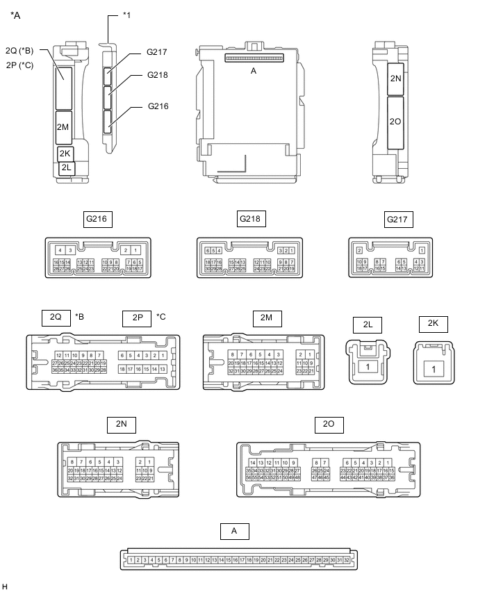
*A Main Body ECU (Multiplex Network Body ECU) with 3 connectors *B for LHD *C for RHD - - *1 Main Body ECU (Multiplex Network Body ECU) - - 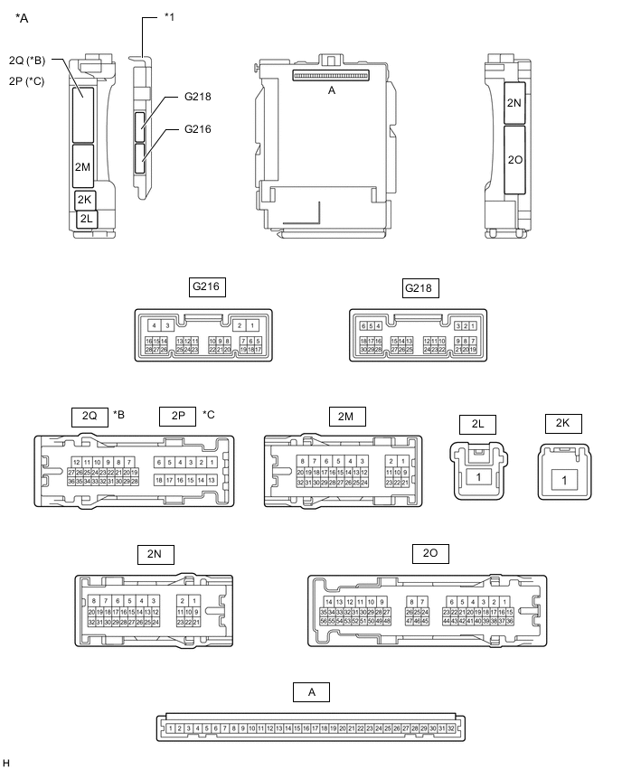
*A Main Body ECU (Multiplex Network Body ECU) with 2 connectors *B for LHD *C for RHD - - *1 Main Body ECU (Multiplex Network Body ECU) - -
-
Remove the main body ECU (multiplex network body ECU).
-
Measure the voltage and resistance according to the value(s) in the table below.
Terminal No. (Symbol) Wiring Color Terminal Description Condition Specified Condition A-31 (BECU) - Body ground - Battery power supply Always 11 to 14 V A-32 (IG) - Body ground - Ignition switch power supply Ignition switch ON 11 to 14 V A-32 (IG) - Body ground - Ignition switch power supply Ignition switch off Below 1 V A-30 (ACC) - Body ground - ACC power supply Ignition switch ACC 11 to 14 V A-30 (ACC) - Body ground - ACC power supply Ignition switch off Below 1 V A-11 (GND1) - Body ground - Ground Always Below 1 Ω -
Install the main body ECU (multiplex network body ECU).
-
Measure the voltage according to the value(s) in the table below.
Terminal No. (Symbol) Wiring Color Terminal Description Condition Specified Condition G218-6 (FLCY) - Body ground R - Body ground Front door LH courtesy switch input Front door LH open Below 1 V G218-6 (FLCY) - Body ground R - Body ground Front door LH courtesy switch input Front door LH closed Pulse generation G218-27 (FRCY) - Body ground B - Body ground Front door RH courtesy switch input Front door RH open Below 1 V G218-27 (FRCY) - Body ground B - Body ground Front door RH courtesy switch input Front door RH closed Pulse generation
-