GLASS HATCH OPENER SYSTEM Glass Hatch Opener System does not Operate
DESCRIPTION
The glass hatch opener system enables the back door glass to be opened when the glass hatch opener switch is pressed.
WIRING DIAGRAM
Figure 1. except 5L-E:
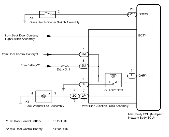
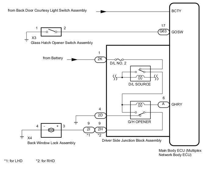
Figure 2. for 5L-E:
CAUTION / NOTICE / HINT
Note
-
Inspect the fuses for circuits related to this system before performing the following inspection procedure.
-
If the main body ECU (multiplex network body ECU) is replaced, refer to the Service Bulletin.*
-
*: w/ Entry and Start System
PROCEDURE
-
CHECK VEHICLE TYPE
-
Check vehicle type.
Result Result Proceed to except 5L-E A for 5L-E B
B 
READ VALUE USING GTS (BACK DOOR COURTESY SW) Click here
A 
-
-
READ VALUE USING GTS (BACK DOOR COURTESY SW)
-
Use the Data List to check if the back door courtesy light switch is functioning properly.
Main Body Tester Display Measurement Item/Range Normal Condition Diagnostic Note Back Door Courtesy SW Back door courtesy switch signal / ON or OFF ON: Back door open
OFF: Back door closed
- OK On the tester screen, item changes between ON and OFF according to above chart. Result Proceed to OK NG
NG 
GO TO LIGHTING SYSTEM Click here
OK
-
-
SYSTEM CHECK
-
Confirm that the vehicle is equipped with the entry and start system.
Result Result Proceed to w/ Entry and Start System A w/o Entry and Start System B
B
GO TO STEP 5 Click here
A
-
-
CHECK ENTRY AND START SYSTEM (for Entry Function)
-
When the back door entry lock switch is operated, check that the glass hatch opens.
OK The back door entry lock function operates normally. Result Proceed to OK NG
NG
GO TO ENTRY AND START SYSTEM (for Entry Function) Click here
OK
-
-
READ VALUE USING GTS (GLASS HATCH OPENER SWITCH)
-
Use the Data List to check if the glass hatch opener switch is functioning properly.
Main Body Tester Display Measurement Item/Range Normal Condition Diagnostic Note Glass Hatch Opener Switch Glass hatch opener switch signal / ON or OFF ON: Glass hatch opener switch operated
OFF: Glass hatch opener switch not operated
- OK Glass hatch opener switch operates. Result Proceed to OK NG
NG
INSPECT GLASS HATCH OPENER SWITCH ASSEMBLY Click here
OK
-
-
PERFORM ACTIVE TEST USING GTS (GLASS HATCH OPEN)
-
Using the GTS, perform the Active Test.
Main Body Tester Display Test Part Control Range Diagnostic Note Glass Hatch Open Operate Glass Hatch ON/OFF - OK The glass hatch is opened. Result Proceed to OK NG
OK
REPLACE MAIN BODY ECU (MULTIPLEX NETWORK BODY ECU) Click here
NG
-
-
INSPECT BACK WINDOW LOCK ASSEMBLY
-
Remove the back window lock assembly.
-
Inspect the back window lock assembly.
Result Proceed to OK NG
NG
REPLACE BACK WINDOW LOCK ASSEMBLY Click here
OK
-
-
CHECK HARNESS AND CONNECTOR (BACK WINDOW LOCK ASSEMBLY - DRIVER SIDE JUNCTION BLOCK ASSEMBLY AND BODY GROUND)
-
Disconnect the X4 back window lock assembly connector.
-
Disconnect the 2Q*1 or 2P*2 driver side junction block assembly connector.
-
*1: for LHD
-
*2: for RHD
-
-
Measure the resistance according to the value(s) in the table below.
Standard Resistance for LHD Tester Connection Condition Specified Condition X4-3 (+) - 2Q-7 Always Below 1 Ω X4-4 (-) - Body ground Always Below 1 Ω X4-3 (+) - Body ground Always 10 kΩ or higher for RHD Tester Connection Condition Specified Condition X4-3 (+) - 2P-7 Always Below 1 Ω X4-4 (-) - Body ground Always Below 1 Ω X4-3 (+) - Body ground Always 10 kΩ or higher Result Proceed to OK NG
NG
REPAIR OR REPLACE HARNESS OR CONNECTOR
OK
-
-
INSPECT DRIVER SIDE JUNCTION BLOCK ASSEMBLY
-
Remove the main body ECU (multiplex network body ECU) from the driver side junction block assembly.
-
Measure the voltage according to the value(s) in the table below.
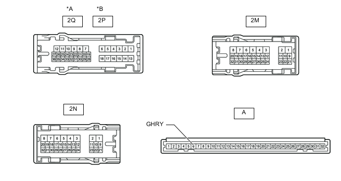
*A for LHD *B for RHD Standard Voltage w/ Door Control Battery *1: for LHDTester Connection Condition Specified Condition 2Q-7 - Battery negative (-) terminal*1
2P-7 - Battery negative (-) terminal*2
Battery not connected to 2M-7 and A-6 (GHRY) Below 1 V Battery positive (+) → 2M-7
Battery negative (-) → A-6 (GHRY)
11 to 14 V
*2: for RHD
w/o Door Control Battery *1: for LHDTester Connection Condition Specified Condition 2Q-7 - Battery negative (-) terminal*1
2P-7 - Battery negative (-) terminal*2
Battery not connected to 2M-8 and A-6 (GHRY) Below 1 V Battery positive (+) → 2M-8
Battery negative (-) → A-6 (GHRY)
11 to 14 V
*2: for RHD
Result Proceed to OK NG
OK
REPLACE MAIN BODY ECU (MULTIPLEX NETWORK BODY ECU) Click here
NG
REPLACE DRIVER SIDE JUNCTION BLOCK ASSEMBLY Click here
-
-
INSPECT GLASS HATCH OPENER SWITCH ASSEMBLY
-
Remove the glass hatch opener switch assembly.
-
Inspect the glass hatch opener switch assembly.
Result Proceed to OK NG
NG
REPLACE GLASS HATCH OPENER SWITCH ASSEMBLY Click here
OK
-
-
CHECK HARNESS AND CONNECTOR (GLASS HATCH OPENER SWITCH ASSEMBLY - MAIN BODY ECU [MULTIPLEX NETWORK BODY ECU] AND BODY GROUND)
-
Disconnect the X3 glass hatch opener switch assembly connector.
-
Disconnect the G216 main body ECU (multiplex network body ECU) connector.
-
Measure the resistance according to the value(s) in the table below.
Standard Resistance Tester Connection Condition Specified Condition X3-2 - G216-28 (GOSW) Always Below 1 Ω X3-1 - Body ground Always Below 1 Ω X3-2 - Body ground Always 10 kΩ or higher Result Proceed to OK NG
OK
REPLACE MAIN BODY ECU (MULTIPLEX NETWORK BODY ECU) Click here
NG
REPAIR OR REPLACE HARNESS OR CONNECTOR
-
-
READ VALUE USING GTS (BACK DOOR COURTESY SW)
-
Use the Data List to check if the back door courtesy light switch is functioning properly.
Main Body Tester Display Measurement Item/Range Normal Condition Diagnostic Note Back Door Courtesy SW Back door courtesy switch signal / ON or OFF ON: Back door open
OFF: Back door closed
- OK On the tester screen, item changes between ON and OFF according to above chart. Result Proceed to OK NG
NG
GO TO LIGHTING SYSTEM Click here
OK
-
-
READ VALUE USING GTS (GLASS HATCH OPENER SWITCH)
-
Use the Data List to check if the glass hatch opener switch is functioning properly.
Main Body Tester Display Measurement Item/Range Normal Condition Diagnostic Note Glass Hatch Opener Switch Glass hatch opener switch signal / ON or OFF ON: Glass hatch opener switch operated
OFF: Glass hatch opener switch not operated
- Result Result Proceed to Glass hatch opener switch does not operate A Glass hatch opener switch operates B
B
PERFORM ACTIVE TEST USING GTS (GLASS HATCH OPEN) Click here
A
-
-
INSPECT GLASS HATCH OPENER SWITCH ASSEMBLY
-
Remove the glass hatch opener switch assembly.
-
Inspect the glass hatch opener switch assembly.
Result Proceed to OK NG
NG
REPLACE GLASS HATCH OPENER SWITCH ASSEMBLY Click here
OK
-
-
CHECK HARNESS AND CONNECTOR (GLASS HATCH OPENER SWITCH ASSEMBLY - MAIN BODY ECU [MULTIPLEX NETWORK BODY ECU] AND BODY GROUND)
-
Disconnect the X3 glass hatch opener switch assembly connector.
-
Disconnect the G63 main body ECU (multiplex network body ECU) connector.
-
Measure the resistance according to the value(s) in the table below.
Standard Resistance Tester Connection Condition Specified Condition X3-2 - G63-17 (GOSW) Always Below 1 Ω X3-1 - Body ground Always Below 1 Ω X3-2 - Body ground Always 10 kΩ or higher Result Proceed to OK NG
OK
REPLACE MAIN BODY ECU (MULTIPLEX NETWORK BODY ECU) Click here
NG
REPAIR OR REPLACE HARNESS OR CONNECTOR
-
-
PERFORM ACTIVE TEST USING GTS (GLASS HATCH OPEN)
-
Using the GTS, perform the Active Test.
Main Body Tester Display Test Part Control Range Diagnostic Note Glass Hatch Open Operate Glass Hatch ON/OFF - OK The glass hatch is opened. Result Proceed to OK NG
OK
REPLACE MAIN BODY ECU (MULTIPLEX NETWORK BODY ECU) Click here
NG
-
-
INSPECT BACK WINDOW LOCK ASSEMBLY
-
Remove the back window lock assembly.
-
Inspect the back window lock assembly.
Result Proceed to OK NG
NG
REPLACE BACK WINDOW LOCK ASSEMBLY Click here
OK
-
-
CHECK HARNESS AND CONNECTOR (BACK WINDOW LOCK ASSEMBLY - DRIVER SIDE JUNCTION BLOCK ASSEMBLY AND BODY GROUND)
-
Disconnect the X4 back window lock assembly connector.
-
Disconnect the 2I*1 or 2H*2 driver side junction block assembly connector.
-
*1: for LHD
-
*2: for RHD
-
-
Measure the resistance according to the value(s) in the table below.
Standard Resistance for LHD Tester Connection Condition Specified Condition X4-3 (+) - 2I-9 Always Below 1 Ω X4-4 (-) - Body ground Always Below 1 Ω X4-3 (+) - Body ground Always 10 kΩ or higher for RHD Tester Connection Condition Specified Condition X4-3 (+) - 2H-9 Always Below 1 Ω X4-4 (-) - Body ground Always Below 1 Ω X4-3 (+) - Body ground Always 10 kΩ or higher Result Proceed to OK NG
NG
REPAIR OR REPLACE HARNESS OR CONNECTOR
OK
-
-
INSPECT DRIVER SIDE JUNCTION BLOCK ASSEMBLY
-
Remove the main body ECU (multiplex network body ECU) from the driver side junction block assembly.
-
Measure the voltage according to the value(s) in the table below.
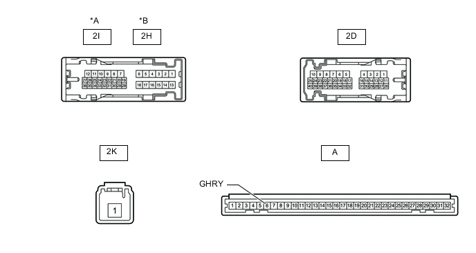
*A for LHD *B for RHD Standard Voltage *1: for LHDTester Connection Condition Specified Condition 2I-9 - Battery negative (-) terminal*1
2H-9 - Battery negative (-) terminal*2
Battery not connected to 2K-1 and A-6 (GHRY) Below 1 V Battery positive (+) → 2K-1
Battery negative (-) → A-6 (GHRY)
11 to 14 V
*2: for RHD
Result Proceed to OK NG
OK
REPLACE MAIN BODY ECU (MULTIPLEX NETWORK BODY ECU) Click here
NG
REPLACE DRIVER SIDE JUNCTION BLOCK ASSEMBLY Click here
-