ROOF HEADLINING(for 5 Door) REMOVAL

CAUTION / NOTICE / HINT
Tech Tips
-
Use the same procedure for RHD and LHD vehicles.
-
The procedure listed below is for LHD vehicles.
PROCEDURE
-
PRECAUTION
Note
After turning the ignition switch off, waiting time may be required before disconnecting the cable from the battery terminal. Therefore, make sure to read the disconnecting the cable from the battery terminal notice before proceeding with work.
-
DISCONNECT CABLE FROM NEGATIVE BATTERY TERMINAL
Note
When disconnecting the cable, some systems need to be initialized after the cable is reconnected.
-
REMOVE REAR NO. 2 SEAT ASSEMBLY (w/ Rear No. 2 Seat)
-
for Manual Seat Type:
-
for Power Seat Type:
-
for Face to Face Seat Type:
-
-
REMOVE REAR NO. 1 SEAT ASSEMBLY (w/ Rear No. 1 Seat)
-
for 60/40 Split Slide Walk-in Seat Type LH Side:
-
for 60/40 Split Slide Walk-in Seat Type RH Side:
-
-
REMOVE REAR NO. 1 SEATBACK ASSEMBLY (w/ Rear No. 1 Seat)
-
for 60/40 Split Double-folding Seat Type LH Side:
-
for 60/40 Split Double-folding Seat Type RH Side:
-
-
REMOVE DOOR SCUFF PLATE ASSEMBLY LH

Protective Tape
-
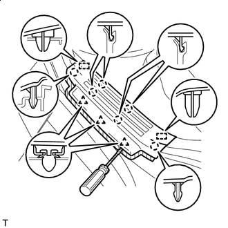
Put protective tape around the door scuff plate assembly LH.
-
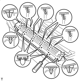
Using a screwdriver, detach the 4 clips, 10 claws and 2 guides and remove the door scuff plate assembly LH.
Tech Tips
Tape the screwdriver tip before use.
-
-
REMOVE DOOR SCUFF PLATE ASSEMBLY RH
Tech Tips
Use the same procedure described for the LH side.
-
REMOVE COWL SIDE TRIM BOARD LH
-
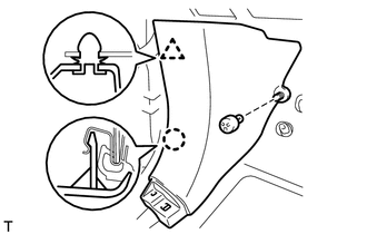
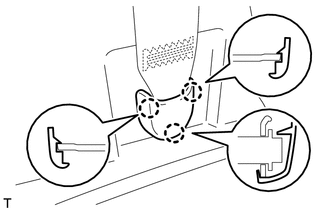
Remove the clip.
-
Detach the clip and claw and remove the cowl side trim board LH.
-
-
REMOVE COWL SIDE TRIM BOARD RH
Tech Tips
Use the same procedure described for the LH side.
-
REMOVE FRONT DOOR OPENING TRIM WEATHERSTRIP LH
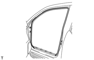
-
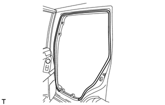
Remove the front door opening trim weatherstrip LH.
-
-
REMOVE FRONT DOOR OPENING TRIM WEATHERSTRIP RH
Tech Tips
Use the same procedure described for the LH side.
-
REMOVE FRONT NO. 1 ASSIST GRIP PLUG LH
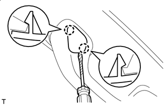
Protective Tape Tech Tips
Use the same procedure for the other front No. 1 assist grip plug.
-
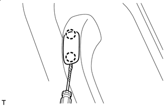
Using a screwdriver, detach the 2 claws and remove the front No. 1 assist grip plug LH.
Tech Tips
Tape the screwdriver tip before use.
-
-
REMOVE FRONT NO. 1 ASSIST GRIP PLUG RH
Tech Tips
Use the same procedure described for the LH side.
-
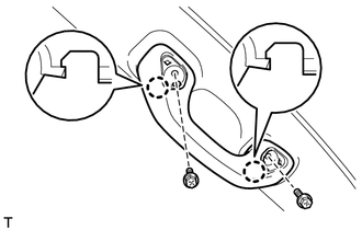
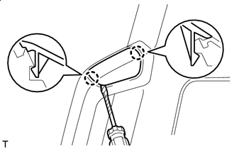
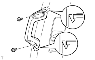
REMOVE NO. 1 ASSIST GRIP
Tech Tips
Use the same procedure for the other No. 1 assist grip.
-
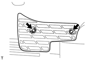
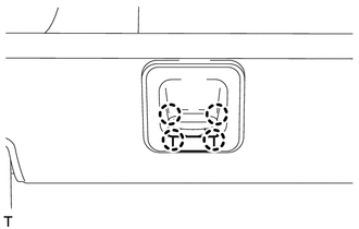
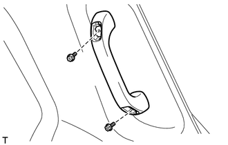
Remove the 2 bolts.
-
Detach the 2 claws and remove the No. 1 assist grip.
-
-
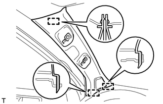
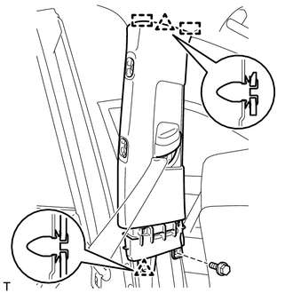
REMOVE FRONT PILLAR GARNISH LH
-
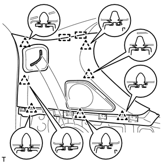
Detach the 3 guides and remove the front pillar garnish LH.
-
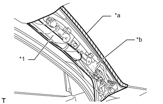
*1 Curtain Shield Airbag Assembly *a Adhesive Tape *b Protective Cover w/ Curtain Shield Airbag:
Protect the curtain shield airbag assembly.
-
Completely cover the airbag with a cloth or nylon sheet and secure the ends of the cover with adhesive tape as shown in the illustration.
Note
Cover the curtain shield airbag with a protective cover as soon as the front pillar garnish is removed.
-
-
-
REMOVE FRONT PILLAR GARNISH RH
Tech Tips
Use the same procedure described for the LH side.
-
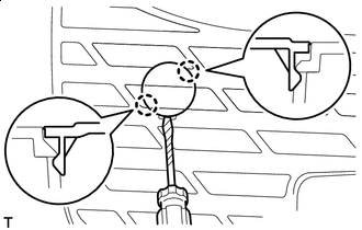
REMOVE REAR NO. 1 FLOOR STEP COVER (w/ Rear No. 2 Seat)
Protective Tape Tech Tips
Use the same procedure for all rear No. 1 floor step covers.
-
Using a screwdriver, detach the 2 claws and remove the rear No. 1 floor step cover.
Tech Tips
Tape the screwdriver tip before use.
-
-
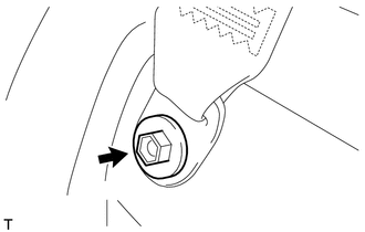
REMOVE INSIDE QUARTER SCUFF PLATE LH (w/ Rear No. 2 Seat)
-
Remove the 2 bolts and inside quarter scuff plate LH.
-
-
REMOVE INSIDE QUARTER SCUFF PLATE RH (w/ Rear No. 2 Seat)
Tech Tips
Use the same procedure described for the LH side.
-
REMOVE REAR DOOR SCUFF PLATE LH
Protective Tape
-
Put protective tape around the rear door scuff plate LH.
-
Using a screwdriver, detach the 3 clips, 6 claws and 2 guides and remove the rear door scuff plate LH.
Tech Tips
Tape the screwdriver tip before use.
-
-
REMOVE REAR DOOR SCUFF PLATE RH
Tech Tips
Use the same procedure described for the LH side.
-
REMOVE REAR DOOR OPENING TRIM WEATHERSTRIP LH
-
Remove the rear door opening trim weatherstrip LH.
-
-
REMOVE REAR DOOR OPENING TRIM WEATHERSTRIP RH
Tech Tips
Use the same procedure described for the LH side.
-
REMOVE OUTER LAP BELT ANCHOR COVER
Tech Tips
Use the same procedure for the other outer lap belt anchor cover.
-
Detach the 3 claws and remove the outer lap belt anchor cover.
-
-
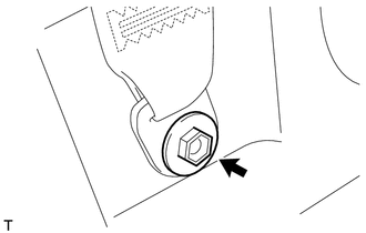
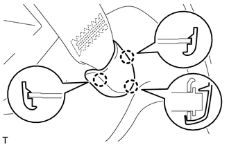
REMOVE LOWER CENTER PILLAR GARNISH LH
-
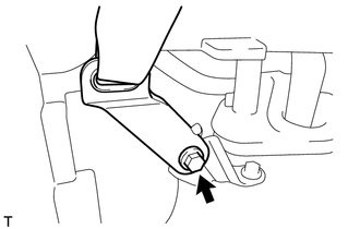
Remove the bolt and disconnect the front seat outer belt floor anchor.
-
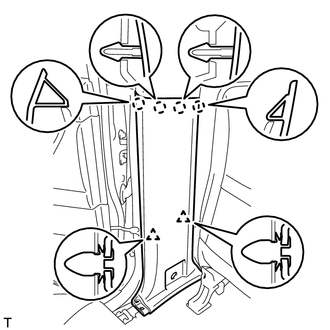
Detach the 4 claws and 2 clips and remove the lower center pillar garnish LH.
-
-
REMOVE LOWER CENTER PILLAR GARNISH RH
Tech Tips
Use the same procedure described for the LH side.
-
REMOVE NO. 2 ASSIST GRIP PLUG LH
Protective Tape Tech Tips
Use the same procedure for the other front No. 2 assist grip plug.
-
Using a screwdriver, detach the 2 claws and remove the front No. 2 assist grip plug LH.
Tech Tips
Tape the screwdriver tip before use.
-
-
REMOVE NO. 2 ASSIST GRIP PLUG RH
Tech Tips
Use the same procedure described for the LH side.
-
REMOVE NO. 2 ASSIST GRIP
Tech Tips
Use the same procedure for the other No. 2 assist grip.
-
Remove the 2 bolts.
-
Detach the 2 claws and remove the No. 2 assist grip.
-
-
REMOVE CENTER PILLAR GARNISH LH
-
Move the front shoulder belt anchor adjuster to the lowest position.
-
Remove the bolt.
-
Detach the 2 clips and 2 guides.
-
Pass the front seat outer belt floor anchor through the center pillar garnish and remove the center pillar garnish LH.
-
-
REMOVE CENTER PILLAR GARNISH RH
Tech Tips
Use the same procedure described for the LH side.
-
REMOVE TONNEAU COVER ASSEMBLY (w/ Tonneau Cover)
-
Remove the tonneau cover assembly.
-
-
REMOVE FRONT LUGGAGE COMPARTMENT TRIM COVER (w/o Rear No. 2 Seat)
Tech Tips
Use the same procedure for the other front luggage compartment trim cover.
-
Detach the 4 claws and remove the cap.
-
*1 Luggage Hold Belt Striker Remove the bolt, luggage hold belt striker and front luggage compartment trim cover.
-
-
REMOVE NO. 1 DECK BOARD SUB-ASSEMBLY (w/o Rear No. 2 Seat)
-
w/o Rear Air Conditioning System:
-
Detach the clip and remove the No. 1 deck board sub-assembly.
-
-
w/ Rear Air Conditioning System:
-
Detach the clip and remove the No. 1 deck board sub-assembly.
-
-
-
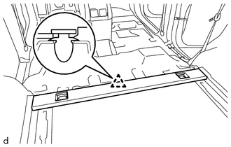
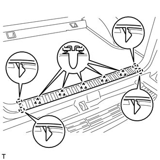
REMOVE REAR FLOOR MAT REAR SUPPORT PLATE (w/o Rear No. 2 Seat)
-
Detach the 5 clips and 4 claws and remove the rear floor mat rear support plate.
-
-
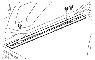
REMOVE FLOOR SIDE RAIL LH (w/ Deck Rail)
-
Remove the 3 bolts and floor side rail LH.
-
-
REMOVE FLOOR SIDE RAIL RH (w/ Deck Rail)
Tech Tips
Use the same procedure described for the LH side.
-
REMOVE REAR FLOOR CARPET ASSEMBLY (w/o Rear No. 2 Seat)
-
Detach the 4 claws and remove the rear floor carpet assembly.
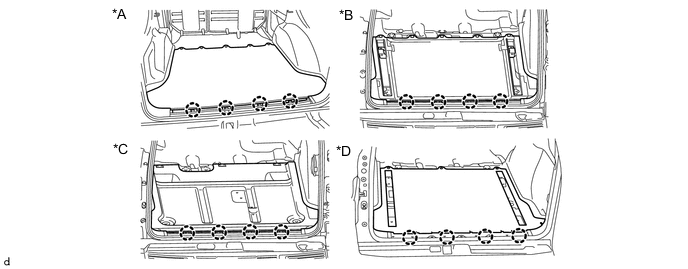
*A w/o Deck Rail *B w/ Deck Rail *C for Face to Face Seat Type *D w/ Rear Air Conditioning System
-
-
REMOVE REAR NO. 1 SEAT OUTER LAP BELT ANCHOR COVER
Tech Tips
Use the same procedure for the other rear No. 1 seat outer lap belt anchor cover.
-
Detach the 3 claws and remove the rear No. 1 seat outer lap belt anchor cover.
-
-
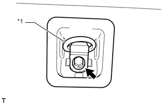
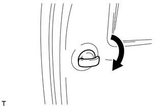
REMOVE NO. 1 LUGGAGE COMPARTMENT TRIM HOOK
Tech Tips
Use the same procedure for the other No. 1 luggage compartment trim hook.
-
Remove the No. 1 luggage compartment trim hook by turning it clockwise.
-
-
REMOVE NO. 1 TONNEAU COVER HOLDER CAP (w/o Tonneau Cover)
Protective Tape Tech Tips
Use the same procedure for the other No. 1 tonneau cover holder cap.
-
Using a screwdriver, detach the 2 claws and remove the No. 1 tonneau cover holder cap.
Tech Tips
Tape the screwdriver tip before use.
-
-
REMOVE FRONT DECK SIDE TRIM COVER (w/ Tonneau Cover)
Protective Tape Tech Tips
Use the same procedure for the other front deck side trim cover.
-
Using a screwdriver, detach the 2 claws and remove the front deck side trim cover.
Tech Tips
Tape the screwdriver tip before use.
-
-
REMOVE ASSIST GRIP PLUG (w/ Rear No. 2 Seat)
Protective Tape Tech Tips
Use the same procedure for all assist grip plugs.
-
Using a screwdriver, detach the 2 claws and remove the assist grip plug.
Tech Tips
Tape the screwdriver tip before use.
-
-
REMOVE ASSIST GRIP SUB-ASSEMBLY (w/ Rear No. 2 Seat)
Tech Tips
Use the same procedure for the other assist grip sub-assembly.
-
Remove the 2 bolts and assist grip sub-assembly.
-
-
REMOVE COOLER THERMISTOR (ROOM TEMPERATURE SENSOR) (w/ Rear Air Conditioning System)
-
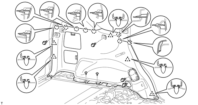
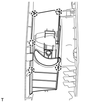
REMOVE DECK TRIM SIDE PANEL ASSEMBLY LH
-
w/o Rear No. 2 Seat, w/o Rear Air Conditioning System:
-
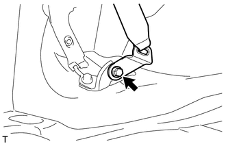
Remove the bolt and disconnect the rear No. 1 seat outer belt floor anchor.
-
Detach the 6 claws and 2 guides and disconnect the rear seatback lock control lever base.
-
Remove the 4 bolts and 2 screws.
-
Detach the 5 clips and 8 claws.
-
Pass the rear seatback lock control lever base through the deck trim side panel assembly and remove the deck trim side panel assembly LH.
-
-
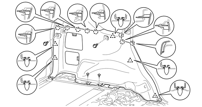
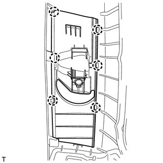
w/o Rear No. 2 Seat, w/ Rear Air Conditioning System:
-
Remove the bolt and disconnect the rear No. 1 seat outer belt floor anchor.
-
Remove the 2 bolts and 2 screws.
-
Detach the 5 clips and 8 claws and remove the deck trim side panel assembly LH.
-
-
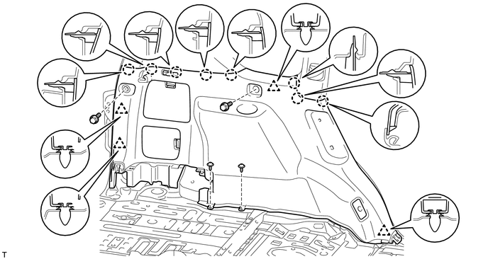
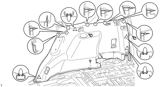
w/ Rear No. 2 Seat:
-
Remove the bolt and disconnect the rear No. 1 seat outer belt floor anchor.
-
Remove the bolt and disconnect the rear No. 2 seat outer belt floor anchor.
-
Remove the 2 bolts and 2 screws.
-
Detach the 4 clips and 8 claws and remove the deck trim side panel assembly LH.
-
-
-
REMOVE DECK TRIM SIDE PANEL ASSEMBLY RH
-
w/o Rear No. 2 Seat, w/o Rear Air Conditioning System:
-
Remove the bolt and disconnect the rear No. 1 seat outer belt floor anchor.
-
Detach the 6 claws and 2 guides and disconnect the rear seatback lock control lever base.
-
Remove the 4 bolts and screws.
-
Detach the 5 clips and 8 claws.
-
Disconnect each connector.
-
Pass the rear seatback lock control lever base through the deck trim side panel and remove the deck trim side panel assembly RH.
-
-
w/o Rear No. 2 Seat, w/ Rear Air Conditioning System:
-
Remove the bolt and disconnect the rear No. 1 seat outer belt floor anchor.
-
Remove the 2 bolts and screws.
-
Detach the 4 clips and 8 claws.
-
Disconnect each connector and remove the deck trim side panel assembly RH.
-
-
w/ Rear No. 2 Seat:
-
Remove the bolt and disconnect the rear No. 1 seat outer belt floor anchor.
-
Remove the bolt and disconnect the rear No. 2 seat outer belt floor anchor.
-
Remove the 2 bolts and screw.
-
Detach the 4 clips and 8 claws.
-
Disconnect each connector and remove the deck trim side panel assembly RH.
-
-
-
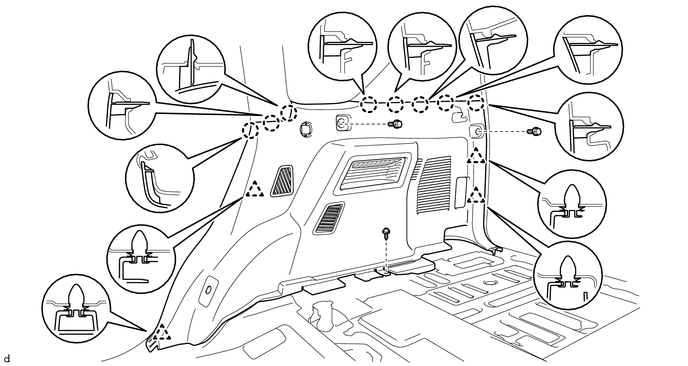
REMOVE FRONT QUARTER TRIM PANEL ASSEMBLY LH
-
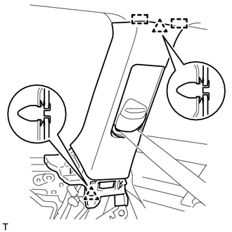
Move the rear shoulder belt anchor adjuster to the lowest position.
-
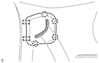
Detach the 2 clips and 2 guides.
-
Pass the rear No. 1 seat outer belt floor anchor through the front quarter trim panel and remove the front quarter trim panel assembly LH.
-
-
REMOVE FRONT QUARTER TRIM PANEL ASSEMBLY RH
Tech Tips
Use the same procedure described for the LH side.
-
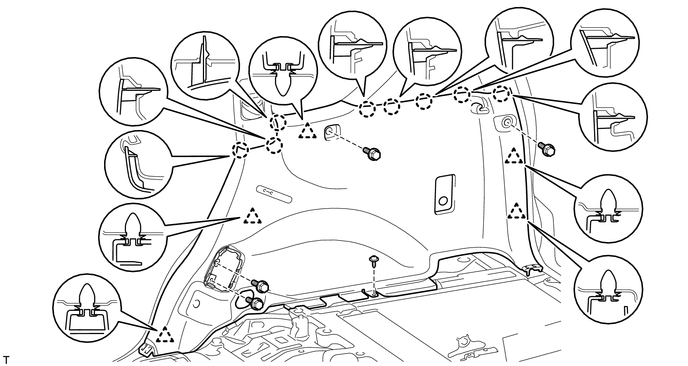
REMOVE REAR QUARTER TRIM PANEL ASSEMBLY LH
-
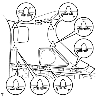
w/o Rear No. 2 Seat:
-
Detach the 7 clips and 2 guides and remove the rear quarter trim panel assembly LH.
-
-
w/ Rear No. 2 Seat:
-
Detach the 7 clips and 2 guides.
-
Detach the 4 clips and 2 guides, pass the rear No. 2 seat outer belt floor anchor through the rear quarter trim panel assembly LH and remove the rear quarter trim panel assembly LH.
-
-
-
REMOVE REAR QUARTER TRIM PANEL ASSEMBLY RH
Tech Tips
Use the same procedure described for the LH side.
-
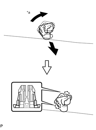
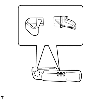
REMOVE ASSIST GRIP SUB-ASSEMBLY
Tech Tips
Use the same procedure for the other assist grip sub-assembly.
-
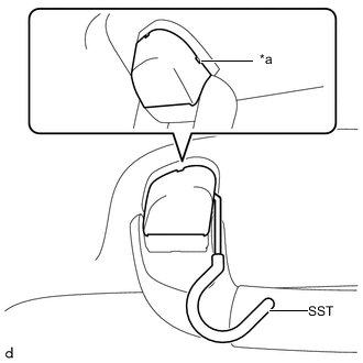
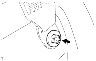
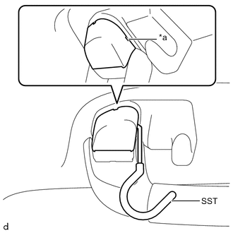
*a Cutout Insert SST into the cutout of the assist grip cover LH as shown in the illustration.
- SST
- 09813-00010
Note
To prevent the assist grip sub-assembly from being damaged, make sure to insert SST straight into the cutout.
Tech Tips
Use the same procedure for the claw on the other side of the assist grip cover LH.
-
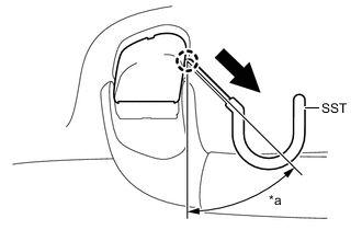
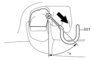
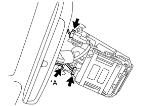
*a 30 to 45° 
Remove in this Direction Pull SST as shown in the illustration to detach the claw.
Note
To prevent the assist grip sub-assembly from being damaged, make sure to only pull SST as shown in the illustration.
Tech Tips
Use the same procedure for the claw on the other side of the assist grip cover LH.
-
Detach the 2 clips and remove the assist grip sub-assembly.
-
-
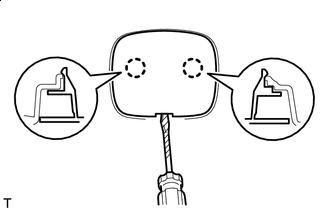
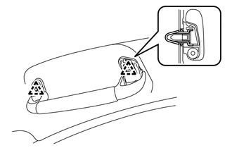
REMOVE REAR ASSIST GRIP ASSEMBLY LH
*a Cutout
-
Insert SST into the cutout of the assist grip cover LH as shown in the illustration.
- SST
- 09813-00010
Note
To prevent the rear assist grip sub-assembly LH from being damaged, make sure to insert SST straight into the cutout.
Tech Tips
Use the same procedure for the claw on the other side of the assist grip cover LH.
-
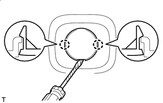
*a 30 to 45° Remove in this Direction Pull SST as shown in the illustration to detach the claw.
Note
To prevent the rear assist grip sub-assembly LH from being damaged, make sure to only pull SST as shown in the illustration.
Tech Tips
Use the same procedure for the claw on the other side of the assist grip cover LH.
-
Detach the 2 clips and remove the rear assist grip sub-assembly LH.
-
-
REMOVE REAR ASSIST GRIP ASSEMBLY RH
Tech Tips
Use the same procedure described for the LH side.
-
REMOVE ASSIST GRIP (w/ Rear No. 2 Seat)
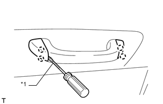
Protective Tape Tech Tips
Use the same procedure for the other assist grip.
-
Using a screwdriver, detach the 4 claws and open the 2 covers.
Tech Tips
Tape the screwdriver tip before use.
-

Remove the 2 bolts and assist grip.
-
-
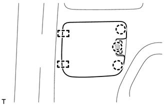
REMOVE MAP LIGHT ASSEMBLY
-
REMOVE RAIN SENSOR COVER (w/ Rain Sensor)
-
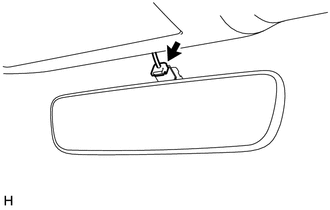
REMOVE INNER REAR VIEW MIRROR STAY HOLDER COVER (w/ EC Mirror)
-
REMOVE NO. 2 FORWARD RECOGNITION COVER (w/ Pre-crash Safety System)
-
REMOVE NO. 1 FORWARD RECOGNITION COVER (w/ Pre-crash Safety System)
-
REMOVE NO. 1 ROOM LIGHT ASSEMBLY
-
REMOVE NO. 2 ROOM LIGHT ASSEMBLY
-
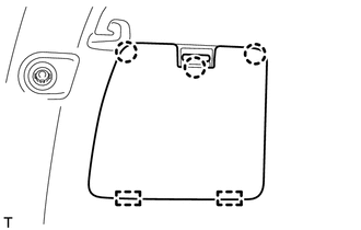
REMOVE TELEVISION BASE (w/ Rear Seat Entertainment System)
-
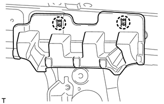
REMOVE REAR SIDE NO. 1 AIR DUCT (w/ Rear Air Conditioning System)
-
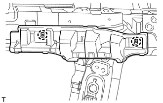
REMOVE REAR HEADER SPEAKER ASSEMBLY (w/ Rear Air Conditioning System)
-
REMOVE VISOR BRACKET COVER LH
Tech Tips
Use the same procedure for the other visor bracket cover.
-
Detach the 4 claws and remove the visor bracket cover LH.
-
-
REMOVE VISOR BRACKET COVER RH
Tech Tips
Use the same procedure described for the LH side.
-
REMOVE VISOR ASSEMBLY LH
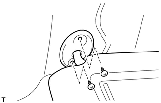
-
Remove the 2 screws and visor assembly LH.
-
-
REMOVE VISOR ASSEMBLY RH
Tech Tips
Use the same procedure described for the LH side.
-
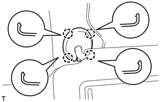
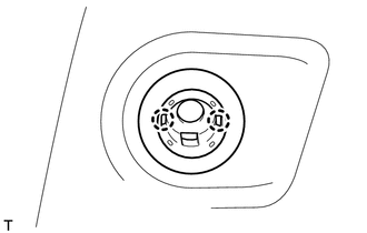
REMOVE VISOR HOLDER
*a 45° Tech Tips
Use the same procedure for the other visor holder.
-
Turn the visor holder approximately 45° and pull it out as shown in the illustration.
-
Detach the 2 claws and remove the visor holder.
-
-
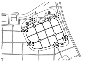
REMOVE ROOF HEADLINING ASSEMBLY
-
*A w/ Camera Heater w/ Pre-crash Safety System:
-
Disconnect the 2 connectors.
-
-
w/ Pre-crash Safety System, w/ Camera Heater:
-
Disconnect the 3 connectors.
-
-
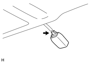
w/ EC Mirror:
-
Disconnect the inner mirror connector.
-
-
w/ Rain Sensor:
-
Disconnect the rain sensor connector.
-
-
w/ Sliding Roof:
-
Disconnect the drive gear connector.
-
-
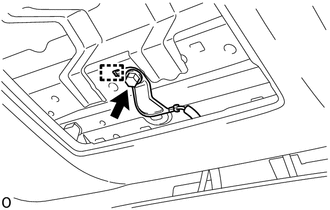
w/ Pre-crash Safety System:
-
Remove the bolt.
-
Detach the hook and disconnect the camera earth.
-
-
w/ Digital Audio Broadcasting Antenna:
-
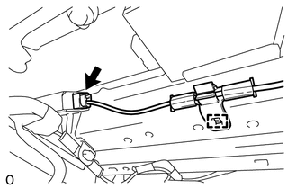
Disconnect the connector and detach the wire harness clamp.
-
-
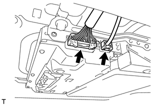
Disconnect the 2 connectors and detach the 3 clamps from the front pillar LH.
-
Remove the bolt.
-
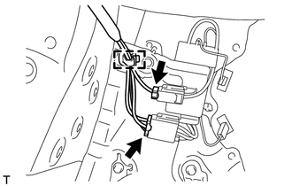
Disconnect the 2 connectors and detach the 3 clamps from the front pillar RH.
-
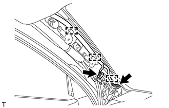
Disconnect the 2 connectors and detach the clamp from the rear pillar LH.
-
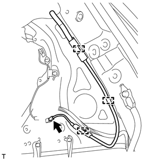
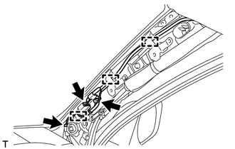
Disconnect the connector and detach the 3 clamps from the rear pillar RH.
-
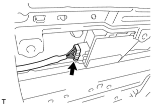
w/ Rear Seat Entertainment System:
-
Disconnect the 2 connectors.
-
-
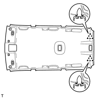
w/o Sliding Roof:
-
Detach the 2 clips.
-
-
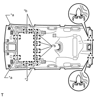
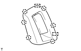
*a Guide *b Fastener w/ Sliding Roof:
-
Detach the 2 clips, 2 guides and 8 fasteners.
-
-
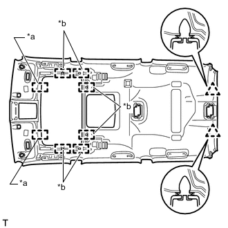
*a Guide *b Fastener w/ Rear Seat Entertainment System:
-
Detach the 2 clips, 2 guides and 6 fasteners.
-
-
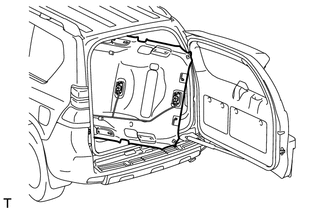
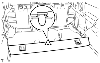
Remove the roof headlining assembly from the back door as shown in the illustration.
Note
Be careful not to damage the roof headlining assembly when removing it.
-
-
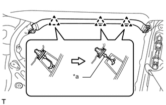
REMOVE FRONT SHOULDER BELT ANCHOR PLATE SUB-ASSEMBLY LH
-
Detach the 5 claws of the front shoulder belt anchor plate sub-assembly LH and slide the front shoulder belt anchor plate sub-assembly LH in the direction of the arrow to remove it.
-
-
REMOVE FRONT SHOULDER BELT ANCHOR PLATE SUB-ASSEMBLY RH
Tech Tips
Use the same procedure described for the LH side.
-
REMOVE REAR SHOULDER BELT ANCHOR PLATE SUB-ASSEMBLY LH
-
Detach the 6 claws of the rear shoulder belt anchor plate sub-assembly LH and slide the rear shoulder belt anchor plate sub-assembly LH in the direction of the arrow to remove it.
-
-
REMOVE REAR SHOULDER BELT ANCHOR PLATE SUB-ASSEMBLY RH
Tech Tips
Use the same procedure described for the LH side.
-
REMOVE NO. 1 ROOF SIDE RAIL GARNISH LH
-
*a Cut Off Position Detach the 3 clips.
-
Cut off the 3 clips and remove the roof side rail garnish LH.
-
Remove 3 clips from the vehicle body.
-
-
REMOVE NO. 1 ROOF SIDE RAIL GARNISH RH
Tech Tips
Use the same procedure described for the LH side.
-
REMOVE ROOF SIDE INNER GARNISH CAP LH (w/o Rear No. 2 Seat)
-
Detach the 4 claws and 2 guides and remove the roof side inner garnish cap LH.
-
-
REMOVE ROOF SIDE INNER GARNISH CAP RH (w/o Rear No. 2 Seat)
Tech Tips
Use the same procedure described for the LH side.
-
REMOVE REAR SEAT SHOULDER BELT HANGER LH
-
Detach the claw and guide and remove the rear seat shoulder belt hanger LH.
-
-
REMOVE REAR SEAT SHOULDER BELT HANGER RH
Tech Tips
Use the same procedure described for the LH side.
-
REMOVE QUARTER TRIM COVER
Tech Tips
Use the same procedure for the other quarter trim cover.
-
Detach the 2 claws and remove the quarter trim cover.
-
-
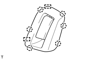
REMOVE QUARTER TRIM JACK COVER
-
Detach the 3 claws and 2 guides and remove the quarter trim jack cover.
-
-
REMOVE DECK SIDE TRIM COVER LH
-
Detach the 3 claws and 2 guides and remove the deck side trim cover LH.
-
-
REMOVE REAR SIDE RAIL SPACER LH (w/o Curtain Shield Airbag)
-
Detach the 2 claws and remove the rear side rail spacer LH.
-
-
REMOVE REAR SIDE RAIL SPACER RH (w/o Curtain Shield Airbag)
Tech Tips
Use the same procedure described for the LH side.
-
REMOVE REAR NO. 2 SIDE RAIL SPACER LH (w/o Curtain Shield Airbag)
-
Detach the 2 claws and remove the rear No. 2 side rail spacer LH.
-
-
REMOVE REAR NO. 2 SIDE RAIL SPACER RH (w/o Curtain Shield Airbag)
Tech Tips
Use the same procedure described for the LH side.
-
REMOVE REAR NO. 3 SIDE RAIL SPACER LH
-
Detach the 2 claws and remove the rear No. 3 side rail spacer LH.
-
-
REMOVE REAR NO. 3 SIDE RAIL SPACER RH
Tech Tips
Use the same procedure described for the LH side.