VISCOUS HEATER MAGNET CLUTCH(for 1GD-FTV) INSTALLATION
PROCEDURE
-
INSTALL VISCOUS HEATER WITH MAGNET CLUTCH ASSEMBLY
-
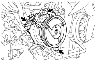
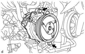
Temporarily install the viscous heater with magnet clutch assembly with the 2 bolts.
-
Connect the connector.
-
-
CONNECT HEATER WATER INLET HOSE
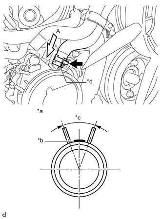
Text in Illustration *a View A *b Paint Marking (Red) *c Clip Installation Angle (40°) *d Rib
-
Align the rib of the viscous heater with magnet clutch assembly with the marking (red). Connect the heater water inlet hose and install the clip within the range shown in the illustration.
Note
Do not apply excessive force to the heater water inlet hose.
-
-
CONNECT HEATER WATER OUTLET HOSE
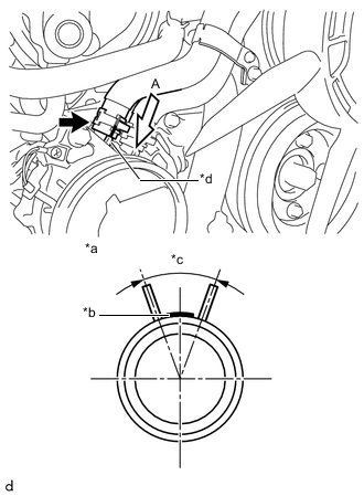
Text in Illustration *a View A *b Paint Marking (Red) *c Clip Installation Angle (40°) *d Rib
-
Align the rib of the viscous heater with magnet clutch assembly with the marking (red). Connect the heater water outlet hose and install the clip within the range shown in the illustration.
Note
Do not apply excessive force to the heater water outlet hose.
-
-
INSTALL FAN SHROUD
-
INSTALL VISCOUS HEATER V BELT
-
Remove the viscous heater V belt Click here.
-
-
TIGHTEN VISCOUS WITH MAGNET CLUTCH HEATER ASSEMBLY
-
Tighten the 2 bolts.
- Torque:
- 39 N*m { 398 kgf*cm, 29 ft.*lbf }
-
-
CONNECT OIL COOLER HOSE (for Automatic Transmission)
-
INSTALL RADIATOR RESERVE TANK ASSEMBLY
-
INSTALL NO. 1 INTERCOOLER AIR HOSE
-
INSTALL NO. 2 RADIATOR HOSE
-
INSTALL NO. 2 INTERCOOLER AIR HOSE
-
INSTALL NO. 1 RADIATOR HOSE
-
INSTALL NO. 3 ENGINE WIRE (for Cold Area)
-
ADD ENGINE COOLANT
-
INSTALL NO. 1 ENGINE UNDER COVER SUB-ASSEMBLY
-
CONNECT CABLE TO NEGATIVE BATTERY TERMINAL (for Cold Area)
Note
When disconnecting the cable, some systems need to be initialized after the cable is reconnected Click here.
-
INSPECT FOR COOLANT LEAK
-
INSTALL UPPER RADIATOR SUPPORT SEAL