HEATER ASSEMBLY INSTALLATION
PROCEDURE
-
INSTALL HEATER BRACKET
-
Attach the guide to install the heater bracket.
-
Install the bolt.
- Torque:
- 9.8 N*m { 100 kgf*cm, 87 in.*lbf }
-
-
INSTALL NO. 1 HEATER BRACKET SUB-ASSEMBLY
-
Install the No. 1 heater bracket sub-assembly with the 3 nuts.
- Torque:
- 16.1 N*m { 164 kgf*cm, 12 ft.*lbf }
-
Attach the clamp to connect the wire harness.
-
-
INSTALL EXHAUST PIPE SUB-ASSEMBLY
-
Install the exhaust pipe sub-assembly Click here.
-
-
INSTALL HEATER AND ACCESSORY ASSEMBLY
-
Install the heater and accessory assembly with the bolt and nut.
- Torque:
- 9.8 N*m { 100 kgf*cm, 87 in.*lbf }
-
Connect the connector.
-
Align the markings on No. 1 heater fuel hose and pipe as shown in the illustration and connect them with the clip.
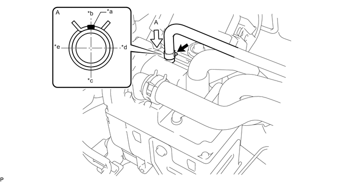
Text in Illustration *a Marking (Yellow) *b Rear Side *c Front Side *d LH Side *e RH Side - - -
Align the markings on each hose and pipe as shown in the illustration and connect them with each clip.
Note
Do not apply excessive force to the hose.
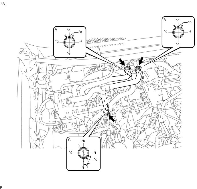
Text in Illustration *A for Dual Air Conditioning System - - *a Marking (Blue) *b Marking (Green) *c Marking (White) *d Upper Side *e Lower Side *f LH Side *g RH Side *h Rear Side *i Front Side *j Clip Installation Angle (30°) 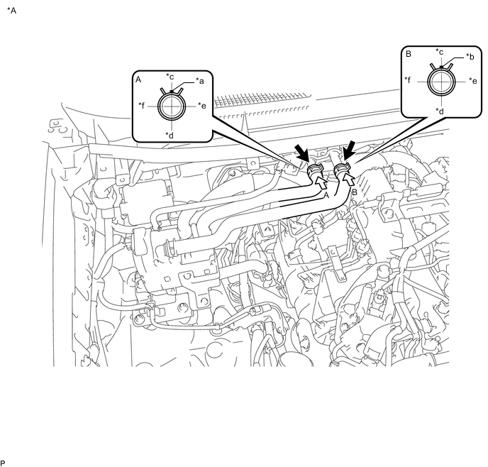
Text in Illustration *A for Single Air Conditioning System - - *a Marking (Blue) *b Marking (Green) *c Upper Side *d Lower Side *e LH Side *f RH Side
-
-
ADD ENGINE COOLANT
-
INSPECT FOR COOLANT LEAK