AIR CONDITIONING PRESSURE SENSOR ON-VEHICLE INSPECTION
PROCEDURE
-
INSPECT NO. 1 PRESSURE SWITCH
-
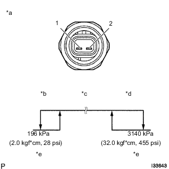
Text in Illustration *a Component without harness connected
(No. 1 Pressure Switch)
*b Low Pressure Side *c On (Below 1.0 Ω) *d High Pressure Side *e Off (10 kΩ or higher) Install a manifold gauge set.
-
Connect the positive (+) lead from the ohmmeter to terminal 1 and the negative (-) lead to terminal 2.
-
Check the resistance between terminals when refrigerant pressure is charged as shown in the illustration.
If operation is not as specified, replace the No. 1 pressure switch.
-
-
INSPECT AIR CONDITIONING PRESSURE SENSOR
-
Install a manifold gauge set.
-
Disconnect the connector from the air conditioning pressure sensor.
-
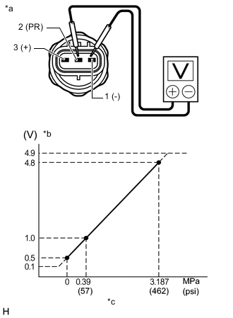
Text in Illustration *a Component without harness connected
(Air Conditioning Pressure Sensor)
*b Voltage *c Refrigerant Pressure Connect the positive (+) lead of a DC 5 V power source to terminal 3 and the negative (-) lead to terminal 1.
-
Connect the positive (+) lead of the voltmeter to terminal 2 and the negative (-) lead to terminal 1.
-
Measure the voltage according to the value(s) in the table below.
Standard Voltage Tester Connection Condition Specified Condition 2 (PR) - 1 (-) Refrigerant pressure:
0.39 to 3.187 MPa (57 to 463 psi)
0.93 to 4.9 V If the result is not as specified, replace the air conditioning pressure sensor.
-