CONDENSER FAN INSTALLATION
CAUTION / NOTICE / HINT
PROCEDURE
-
INSTALL SHROUD BLOWER ASSEMBLY
-
Install the shroud blower assembly with the bolt.
- Torque:
- 5.4 N*m { 55 kgf*cm, 48 in.*lbf }
-
Connect the connector.
-
-
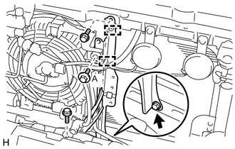
INSTALL AIR CONDITIONING TUBE ASSEMBLY
-
Remove the attached vinyl tape from the air conditioning tube assembly.
-
Sufficiently apply compressor oil to a new O-ring and the fitting surface of the cooler condenser assembly.
Compressor oil ND-OIL 8 or equivalent -
Install the O-ring to the air conditioning tube assembly.
-
Attach the clamp to install the air conditioning tube assembly.
-
Install the 2 bolts.
- Torque:
- 5.4 N*m { 55 kgf*cm, 48 in.*lbf }
-
Connect the connector.
-
-
INSTALL HOOD LOCK SUPPORT BRACE SUB-ASSEMBLY
-
Install the hood lock support brace sub-assembly with the 4 bolts.
- Torque:
- Bolt A
- 5.4 N*m { 55 kgf*cm, 48 in.*lbf }
-
Attach the each clamp.
-
-
INSTALL HOOD LOCK ASSEMBLY
-
for LHD:
Install the hood lock assembly Click here.
-
for RHD:
Install the hood lock assembly Click here.
-
-
INSTALL HOOD LOCK RELEASE LEVER PROTECTOR
-
INSTALL MILLIMETER WAVE RADAR SENSOR ASSEMBLY (w/ Dynamic Radar Cruise Control System)
-
INSTALL RADIATOR GRILLE
-
CHARGE REFRIGERANT
-
WARM UP ENGINE
-
CHECK FOR REFRIGERANT GAS LEAK
-
ADJUST MILLIMETER WAVE RADAR SENSOR ASSEMBLY (w/ Dynamic Radar Cruise Control System)
-
INSTALL UPPER RADIATOR SUPPORT SEAL