COMPRESSOR(for 2TR-FE) INSTALLATION

PROCEDURE
-
ADJUST COMPRESSOR OIL
-
When replacing the compressor and magnet clutch with a new one, gradually discharge the refrigerant gas from the service valve and drain the following amount of oil from the new compressor and magnet clutch before installation.
Standard for Single Air Conditioning System: (The amount of oil inside a new cooler compressor: 120 to 135 cc (4.1 to 4.6 fl. oz.)) - (The amount of oil remaining in the removed cooler compressor) = (The amount of oil to be removed when replacing the compressor) Standard for Dual Air Conditioning System: (The amount of oil inside a new cooler compressor: 180 to 195 cc (6.1 to 6.6 fl. oz.)) - (The amount of oil remaining in the removed cooler compressor) = (The amount of oil to be removed when replacing the compressor) Note
-
When checking the compressor oil level, follow the A/C system precautions.
-
Since compressor oil remains in the pipes of the vehicle, if a new compressor is installed without removing some oil from the compressor, the oil amount becomes excessive. Excessive oil prevents heat exchange in the refrigerant cycle and causes refrigeration system failure.
-
If the volume of oil remaining in the removed compressor and magnet clutch is small, check for oil leakage.
-
Be sure to use ND-OIL 8 or equivalent compressor oil.
-
-
-
INSTALL COOLER COMPRESSOR ASSEMBLY
-
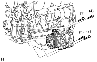
Install the compressor with the 4 bolts and tighten the bolts in the order shown in the illustration.
- Torque:
- 25 N*m { 255 kgf*cm, 18 ft.*lbf }
-
Connect the connector.
-
-
INSTALL SUCTION HOSE SUB-ASSEMBLY
-
Remove the vinyl tape attached to the hose.
-
Sufficiently apply compressor oil to a new O-ring and the fitting surface of the compressor.
Compressor oil ND-OIL 8 or equivalent -
Install the O-ring to the suction hose.
-
Connect the suction hose with the bolt.
- Torque:
- 9.8 N*m { 100 kgf*cm, 87 in.*lbf }
-
-
INSTALL DISCHARGE HOSE SUB-ASSEMBLY
-
Remove the vinyl tape attached to the hose.
-
Sufficiently apply compressor oil to a new O-ring and the fitting surface of the compressor.
Compressor oil ND-OIL 8 or equivalent -
Install the O-ring to the discharge hose.
-
Connect the discharge hose with the bolt.
- Torque:
- 9.8 N*m { 100 kgf*cm, 87 in.*lbf }
-
-
CONNECT VANE PUMP ASSEMBLY
-
INSTALL FAN SHROUD
-
INSTALL NO. 2 RADIATOR HOSE
-
INSTALL NO. 1 RADIATOR HOSE
-
INSTALL RADIATOR RESERVOIR
-
INSTALL FAN AND GENERATOR V BELT
-
INSTALL NO. 1 ENGINE UNDER COVER SUB-ASSEMBLY
-
INSTALL FRONT BUMPER COVER LOWER
-
CHARGE REFRIGERANT
-
ADD ENGINE COOLANT
-
WARM UP ENGINE
-
CHECK FOR REFRIGERANT LEAK
-
INSTALL UPPER RADIATOR SUPPORT SEAL