COMPRESSOR(for 1KD-FTV) INSTALLATION

PROCEDURE
-
INSTALL COOLER COMPRESSOR ASSEMBLY
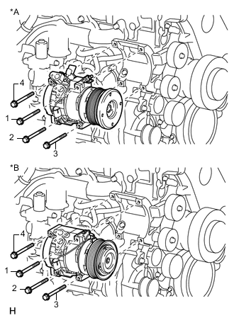
Text in Illustration *A except Cold Area Specification Vehicles *B for Cold Area Specification Vehicles
-
Temporarily install the cooler compressor with the 4 bolts.
Tech Tips
Tighten the bolts in the order shown in the illustration.
-
Tighten the 4 bolts.
- Torque:
- 25 N*m { 255 kgf*cm, 18 ft.*lbf }
Note
Tighten the bolts in the order shown in the illustration to install the cooler compressor.
-
-
INSTALL NO. 1 COOLER REFRIGERANT SUCTION HOSE
-
Remove the attached vinyl tape from the hose.
-
Sufficiently apply compressor oil to a new O-ring and the fitting surface of the cooler compressor.
Compressor oil ND-OIL 8 or equivalent -
Install the O-ring to the suction hose.
-
Connect the suction hose to the cooler compressor with the bolt.
- Torque:
- 9.8 N*m { 100 kgf*cm, 87 in.*lbf }
-
-
INSTALL NO. 1 COOLER REFRIGERANT DISCHARGE HOSE
-
Remove the attached vinyl tape from the hose.
-
Sufficiently apply compressor oil to a new O-ring and the fitting surface of the cooler compressor.
Compressor oil ND-OIL 8 or equivalent -
Install the O-ring to the discharge hose.
-
Connect the discharge hose to the cooler compressor with the bolt.
- Torque:
- 9.8 N*m { 100 kgf*cm, 87 in.*lbf }
-
-
INSTALL NO. 1 VISCOUS HEATER BRACKET SUB-ASSEMBLY (w/ Viscous Heater)
-
INSTALL VISCOUS WITH MAGNET CLUTCH HEATER ASSEMBLY (w/ Viscous Heater)
-
INSTALL FAN AND GENERATOR V BELT
-
INSTALL COMPRESSOR OUTLET ELBOW
-
INSTALL AIR CLEANER CASE SUB-ASSEMBLY
-
INSTALL AIR CLEANER FILTER ELEMENT SUB-ASSEMBLY
-
INSTALL AIR CLEANER CAP SUB-ASSEMBLY
-
INSTALL NO. 1 AIR CLEANER HOSE
-
INSTALL BATTERY TRAY
-
INSTALL BATTERY
-
INSTALL BATTERY HOLD DOWN CLAMP
-
INSTALL RADIATOR RESERVOIR
-
Connect the No. 2 water by-pass hose to the radiator reservoir.
-
Connect the No. 1 water by-pass hose to the fan shroud and attach the 2 clamps.
-
Install the radiator reservoir assembly with the 3 bolts.
- Torque:
- 5.0 N*m { 51 kgf*cm, 44 in.*lbf }
-
-
CONNECT CABLE TO NEGATIVE BATTERY TERMINAL
Note
When disconnecting the cable, some systems need to be initialized after the cable is reconnected Click here.
-
ADD ENGINE COOLANT
-
INSTALL NO. 1 ENGINE UNDER COVER SUB-ASSEMBLY
-
CHARGE REFRIGERANT
-
WARM UP ENGINE
-
CHECK FOR REFRIGERANT GAS LEAK
-
INSTALL UPPER RADIATOR SUPPORT SEAL