REAR AIR CONDITIONING UNIT REASSEMBLY
PROCEDURE
-
INSTALL AIR CONDITIONING HARNESS ASSEMBLY
-
INSTALL REAR EVAPORATOR TEMPERATURE SENSOR
-
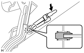
Attach the 2 claws to install the sensor.
-
Move the tip of the sensor in the direction indicated by the arrow in the illustration to install it to the bracket plate.
-
-
INSTALL REAR EVAPORATOR SUB-ASSEMBLY
-
Sufficiently apply compressor oil to 2 new O-rings and the fitting surface of the hose joint.
Refrigerant Compressor Oil HFC-134a (R134a) ND-OIL 8 or equivalent HFO-1234yf (R1234yf) ND-OIL 12 or equivalent -
Install the 2 O-rings to the evaporator.
-
Install the evaporator to the rear cooling unit case RH.
-
-
INSTALL REAR COOLING UNIT EXPANSION VALVE
-
Install the expansion valve.
-
Using a 4 mm hexagon wrench, install the 2 hexagon bolts.
- Torque:
- 3.5 N*m { 36 kgf*cm, 31 in.*lbf }
-
Install the rear cooling unit case LH with the 12 screws.
-
Attach the 3 clamps.
-
Attach the 2 clamps and install the air conditioning wiring harness to the rear cooling unit case.
-
-
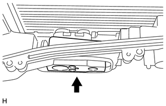
INSTALL BLOWER MOTOR CONTROLLER
-
Install the blower motor controller with the 2 screws.
-
-
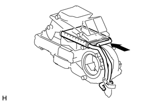
INSTALL REAR BLOWER WITH FAN MOTOR SUB-ASSEMBLY
-
Install the rear blower with fan motor with the 3 screws.
-
-
INSTALL HEATER BRACKET
-
Install the bracket with the 3 screws.
-
-
INSTALL HEATER RADIATOR UNIT SUB-ASSEMBLY
-
Attach the 2 claws to install the heater clamp.
-
Install the radiator unit to the rear cooling unit.
-
Attach the claw to close the heater clamp.
-
Install the screw.
-
-
INSTALL AIR CONDITIONING TUBE AND ACCESSORY ASSEMBLY
-
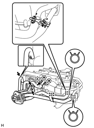
Sufficiently apply compressor oil to 2 new O-rings and the fitting surface of the hose joint.
Refrigerant Compressor Oil HFC-134a (R134a) ND-OIL 8 or equivalent HFO-1234yf (R1234yf) ND-OIL 12 or equivalent -
Install the 2 O-rings to the air conditioning accessory assembly.
-
Install the air conditioning accessory assembly.
-
Align the white marks on the hoses with the black marks on the pipes and install the air conditioning accessory assembly to the rear cooling unit.
-
Using pliers, grip the claws of the clips and slide the 2 clips.
Note
When installing the clips, align the protruding parts of the clips with the white marks of the hoses.
-
Attach the clamp.
-
Install the bolt and 2 screws.
- Torque:
- 5.4 N*m { 55 kgf*cm, 48 in.*lbf }
-
Attach the 3 claws to install the cover.
-
Align the cutout of the hose with the protrusion of the unit and connect the drain hose.
-
Install new packing.
-
-
INSTALL REAR MODE DAMPER SERVO SUB-ASSEMBLY
-
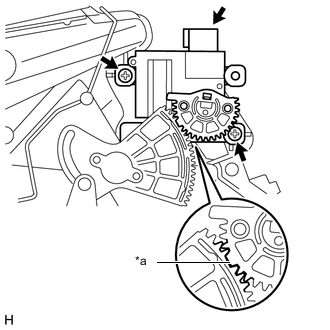
Text in Illustration *a Alignment Point Align the damper servo as shown in the illustration and install it with the 2 screws.
-
Connect the connector.
-
-
INSTALL COOLER BRACKET
-
Install the bracket with the 4 screws.
-
-
INSTALL REAR AIR MIX DAMPER SERVO SUB-ASSEMBLY
-
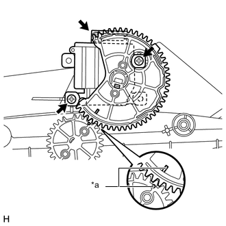
Text in Illustration *a Alignment Point Position the air mix damper servo so that the large tooth of the gear engages with the cutout part as shown in the illustration and install the air mix damper servo with the 2 screws.
-
Connect the connector.
-
-
INSTALL REAR SIDE NO. 4 AIR DUCT (w/ Rear Air Duct)
-
Install the duct with the 3 screws.
-