COMBUSTION TYPE POWER HEATER SYSTEM Power Heater Alternator Circuit
DESCRIPTION
The heater assembly receives engine operation signals from the air conditioning amplifier assembly. If this circuit is open, the heater assembly will determine that the engine operation signals indicate on. If this circuit is shorted, the heater assembly will determine that the engine operation signals indicate off and the heater assembly will not operate.
WIRING DIAGRAM
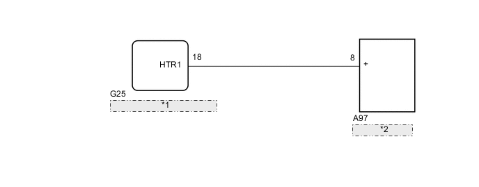
| *1 | Air Conditioning Amplifier Assembly |
| *2 | Heater Assembly |
PROCEDURE
-
CHECK HARNESS AND CONNECTOR (HEATER ASSEMBLY - AIR CONDITIONING AMPLIFIER ASSEMBLY)
-
Disconnect the A97 heater assembly connector.
-
Disconnect the G25 air conditioning amplifier assembly connector.
-
Measure the resistance according to the value(s) in the table below.
Standard Resistance Tester Connection Condition Specified Condition A97-8 (+) - G25-18 (HTR1) Always Below 1 Ω A97-8 (+) - Body ground Always 10 kΩ or higher
NG 
REPAIR OR REPLACE HARNESS OR CONNECTOR
OK 
-
-
CHECK HEATER ASSEMBLY
-
Disconnect the G25 air conditioning amplifier assembly connector.
-
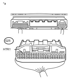
Text in Illustration *a Rear view of wire harness connector
(to Air Conditioning Amplifier Assembly)
Measure the voltage according to the value(s) in the table below.
Standard Voltage Tester Connection Condition Specified Condition G25-18 (HTR1) - Body ground Engine idling, heater switch assembly (power heater switch) off Below 1 V Engine idling, heater switch assembly (power heater switch) on 11 to 14 V
NG
REPLACE HEATER ASSEMBLY Click here
OK
-
-
CHECK AIR CONDITIONING AMPLIFIER ASSEMBLY
-
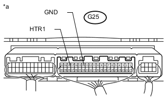
Text in Illustration *a Component with harness connected
(Air Conditioning Amplifier Assembly)
Remove the air conditioning amplifier assembly with its connectors still connected Click here
-
Measure the voltage according to the value(s) in the table below.
Standard Voltage Tester Connection Condition Specified Condition G25-18 (HTR1) - G25-14 (GND) Engine idling 11 to 14 V
OK
PROCEED TO NEXT SUSPECTED AREA SHOWN IN PROBLEM SYMPTOMS TABLE Click here
NG
REPLACE AIR CONDITIONING AMPLIFIER ASSEMBLY Click here
-