AIR CONDITIONING SYSTEM(for Manual Air Conditioning System) Rear Air Conditioning Control Panel Circuit
DESCRIPTION
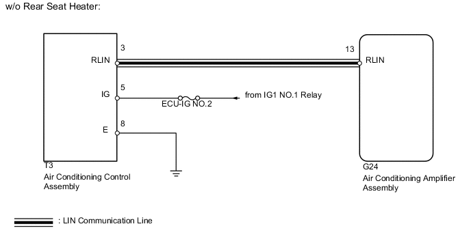
This circuit consists of the air conditioning control assembly and air conditioning amplifier. When the air conditioning control assembly is operated, signals are transmitted to the air conditioning amplifier through the LIN communication system.
If the LIN communication system malfunctions, the air conditioning amplifier does not operate even if the air conditioning control assembly is operated.
WIRING DIAGRAM

CAUTION / NOTICE / HINT
Note
Inspect the fuses for circuits related to this system before performing the following inspection procedure.
PROCEDURE
-
CHECK VEHICLE TYPE
-
Check the vehicle type.
Result Result Proceed to w/o Rear Seat Heater A w/ Rear Seat Heater B
B 
CHECK HARNESS AND CONNECTOR (AIR CONDITIONING CONTROL - AIR CONDITIONING AMPLIFIER) Click here
A 
-
-
CHECK HARNESS AND CONNECTOR (AIR CONDITIONING CONTROL - AIR CONDITIONING AMPLIFIER)
-
Disconnect the G24 amplifier connector.
-
Disconnect the T3 control connector.
-
Measure the resistance according to the value(s) in the table below.
Standard Resistance Tester Connection Condition Specified Condition T3-3 (RLIN) - G24-13 (RLIN) Always Below 1 Ω T3-3 (RLIN) - Body ground Always 10 kΩ or higher
NG 
REPAIR OR REPLACE HARNESS OR CONNECTOR
OK
-
-
CHECK HARNESS AND CONNECTOR (AIR CONDITIONING CONTROL - BATTERY AND BODY GROUND)
-
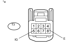
Text in Illustration *a Front view of wire harness connector
(to Air Conditioning Control Assembly)
Disconnect the T3 control connector.
-
Measure the voltage according to the value(s) in the table below.
Standard Voltage Tester Connection Switch Condition Specified Condition T3-5 (IG) - T3-8 (E) Ignition switch off Below 1 V T3-5 (IG) - T3-8 (E) Ignition switch ON 11 to 14 V -
Measure the resistance according to the value(s) in the table below.
Standard Resistance Tester Connection Condition Specified Condition T3-8 (E) - Body ground Always Below 1 Ω
NG
REPAIR OR REPLACE HARNESS OR CONNECTOR
OK
-
-
CHECK AIR CONDITIONING CONTROL ASSEMBLY
-
Replace the air conditioning control assembly with a new or normally functioning one Click here.
-
Operate the air conditioning control assembly to check that it functions properly.
OK Air conditioning control assembly operates normally.
OK
END (AIR CONDITIONING CONTROL ASSEMBLY IS FAULTY)
NG
PROCEED TO NEXT SUSPECTED AREA SHOWN IN PROBLEM SYMPTOMS TABLE Click here
-
-
CHECK HARNESS AND CONNECTOR (AIR CONDITIONING CONTROL - AIR CONDITIONING AMPLIFIER)
-
Disconnect the G24 amplifier connector.
-
Disconnect the T7 control connector.
-
Measure the resistance according to the value(s) in the table below.
Standard Resistance Tester Connection Condition Specified Condition T7-6 (RLIN) - G24-13 (RLIN) Always Below 1 Ω T7-6 (RLIN) - Body ground Always 10 kΩ or higher
NG
REPAIR OR REPLACE HARNESS OR CONNECTOR
OK
-
-
CHECK HARNESS AND CONNECTOR (AIR CONDITIONING CONTROL - BATTERY AND BODY GROUND)
-
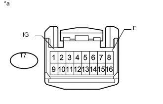
Text in Illustration *a Front view of wire harness connector
(to Air Conditioning Control Assembly)
Disconnect the T7 control connector.
-
Measure the voltage according to the value(s) in the table below.
Standard Voltage Tester Connection Switch Condition Specified Condition T7-1 (IG) - T7-8 (E) Ignition switch off Below 1 V T7-1 (IG) - T7-8 (E) Ignition switch ON 11 to 14 V -
Measure the resistance according to the value(s) in the table below.
Standard Resistance Tester Connection Condition Specified Condition T7-8 (E) - Body ground Always Below 1 Ω
NG
REPAIR OR REPLACE HARNESS OR CONNECTOR
OK
-
-
CHECK AIR CONDITIONING CONTROL ASSEMBLY
-
Replace the air conditioning control assembly with a new or normally functioning one Click here.
-
Operate the air conditioning control assembly to check that it functions properly.
OK Air conditioning control assembly operates normally.
OK
END (AIR CONDITIONING CONTROL ASSEMBLY IS FAULTY)
NG
PROCEED TO NEXT SUSPECTED AREA SHOWN IN PROBLEM SYMPTOMS TABLE Click here
-